A fixed shaft hybrid transmission with integrated drive motor

A technology of integrated drive and hybrid power, which is applied to the layout of multiple different prime movers of hybrid vehicles, power plants, and general power plants. It can solve the problem of small axial layout space and achieve good adaptability to working conditions. The effect of simple shaft system and simplified gear shaft

Active Publication Date: 2017-12-26
TONGJI UNIV
View PDF2 Cites 1 Cited by
  • Summary
  • Abstract
  • Description
  • Claims
  • Application Information

AI Technical Summary

Problems solved by technology

However, this patent needs to set up a three-port assembly with a relatively complex structure to realize the path switching of the motor power coupling. At the same time, there is no reverse speed ratio between the input shaft and the output shaft. The axial layout space is small

Method used


Image

  • A fixed shaft hybrid transmission with integrated drive motor
  • A fixed shaft hybrid transmission with integrated drive motor
  • A fixed shaft hybrid transmission with integrated drive motor

Examples


Embodiment 1

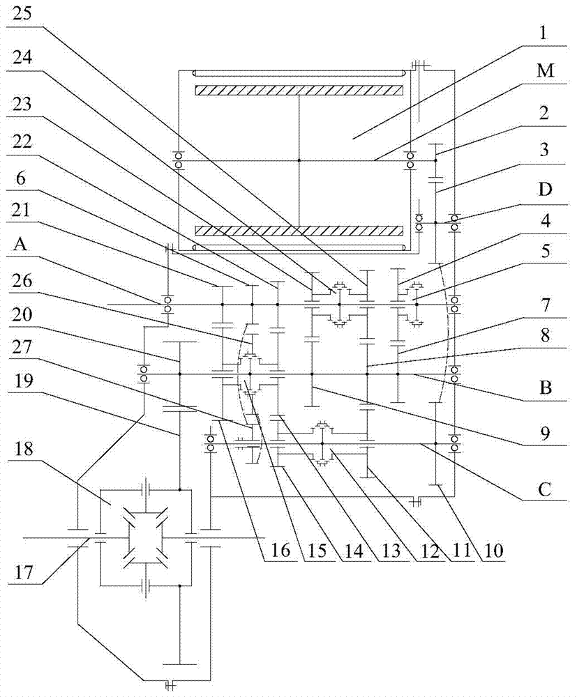
[0047] A fixed-shaft hybrid transmission integrated with a drive motor, its structure is as follows figure 1As shown, it includes 5 transmission shafts, namely: motor shaft M consolidated with the motor rotor, motor idler shaft D, input shaft A for transmitting the output power of the engine, output shaft B and the The reverse gear shaft C used to realize the reverse speed ratio from input to output, and two drive shafts 17, the above seven shafts are arranged in parallel, the reverse gear shaft C is first coupled with the output shaft B, through the reverse gear sliding gear 27 Realize the reverse speed ratio.

[0048] There are 5 forward speed ratios in total between the input shaft A and the output shaft B, wherein the 1st gear driving gear 21, the 2nd gear driving gear 22, the 5th gear driven gear 7, the 4th gear driven gear 8, and the 3rd gear driven gear The gear 9 is fixed with the input shaft A and the output shaft B respectively, the driving gear 23 of the 3rd gear, ...

Embodiment 2

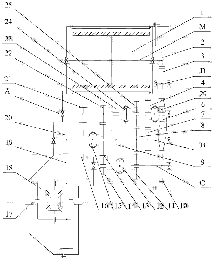
[0055] A fixed-shaft hybrid transmission integrated with a drive motor, its structure is as follows figure 2 As shown, compared with Embodiment 1, the main difference lies in the implementation of the mechanical reverse gear. In Embodiment 2, the reverse driving gear 6 is idly sleeved on the input shaft A, and it meshes with the motor power coupling gear 10 . The switching between the 5 / reverse gears is realized by the 5 / reverse gear synchronizer 29 . When the 5 / reverse gear synchronizer 29 and the mode switch synchronizer 12 respectively connect the reverse gear drive gear 6 and the motor output shaft gear 11 to the input shaft A and the reverse gear shaft C, the power output by the engine passes through the reverse drive gear 6. The motor power coupling gear 10, the motor output shaft gear 11 and the 4th gear driven gear 8 are transmitted to the output shaft B, thereby realizing the reverse speed ratio from input to output, that is, mechanical reverse gear. Under differen...

Embodiment 3

[0060] A fixed-shaft hybrid transmission integrated with a drive motor, its structure is as follows Figure 4 As shown, compared with Embodiment 2, the main difference lies in the implementation of the mechanical reverse gear. In embodiment 3, the switching of 5 / reverse gear is no longer realized through the same synchronizer. The reverse gear driving gear 6 is fixed with the input shaft A, and the reverse gear synchronizer 28 can connect the reverse gear idler gear 32 meshed with the reverse gear driving gear 6 to the reverse gear shaft C in rotational driving connection.


PUM


Abstract

The invention relates to a fixed-shaft type hybrid power transmission for an integrated drive motor. The fixed-shaft type hybrid power transmission comprises input shafts in drive connection with an internal combustion engine, output shafts keeping rotary drive connection with wheels through a differential mechanism, a reverse gear shaft, the integrated motor, gear pairs and synchronizers, wherein a plurality of input shafts and output shafts are formed by idler gear-synchronizer-consolidation gear pairs, a mutual exclusive forward speed ratio is formed between the input shafts and the output shafts, the reverse gear shaft is formed by a plurality of reveres gears, the reverse speed ratio from input to output is formed by the reverse gear shaft and can be cut off, and the integrated motor is connected with the input shafts, the output shafts and the reverse gear shaft in a driving mode through the gear pairs and the synchronizers. Compared with the prior art, while the variable power transfer path of the motor is achieved, axial and radial arrangement space of the motor can be effectively increased, and the fixed-shaft type hybrid power transmission is suitable for being applied to strong-mixing and plug-in hybrid electric vehicles.

Description

technical field [0001] The invention relates to an automobile transmission, in particular to a fixed shaft hybrid transmission integrated with a drive motor. Background technique [0002] Common single-motor fixed-axis parallel hybrid electric vehicle drive trains mainly include two types, namely P2 and P3 schemes. In the P2 scheme, the motor is located at the input end of the transmission, so as to make full use of the transmission ratio to achieve high-efficiency transmission. In the P3 scheme, the motor is located at the output end of the transmission, so that the vehicle can shift gears without power interruption. For the above two solutions, the motor can only transmit power to the wheel through a limited number of fixed paths. At present, there is a relatively advanced single-motor fixed-axis parallel hybrid electric vehicle. The core design idea is to make the motor have a variable power transmission path, that is, the motor can be optionally connected to the input ...

Claims


Application Information

Patent Timeline
Patent Type & Authority Patents(China)
IPC IPC(8): B60K6/547
CPCY02T10/62
Inventor 钟再敏余卓平陈辛波吴海康陈雪平
Owner TONGJI UNIV
Why Eureka
Try Eureka