
A continuous autoclave method

A technology of autoclaving and autoclaving, which is applied to conveyor objects, furnaces, packaging, etc., can solve problems such as low energy utilization efficiency, low efficiency, and reduced production efficiency, and achieve the effect of improving production efficiency and energy utilization rate.

Active Publication Date: 2016-11-30
SHANDONG AGRI UNIV FERTILIZER TECH CO LTD
View PDF7 Cites 0 Cited by
  • Summary
  • Abstract
  • Description
  • Claims
  • Application Information

AI Technical Summary

Problems solved by technology

[0002] The existing autoclaving device generally includes a pressure cylinder and a cover at both ends of the pressure cylinder. When feeding is required, open the cover at one end, put the material into the pressure cylinder, and then autoclave. Pressure relief, because the pressure relief time is long, and continuous production cannot be performed during the pressure relief process, resulting in low efficiency, especially for materials with a long reaction time, which seriously affects the normal operation of other processes and significantly reduces production efficiency, and the above-mentioned Due to the intermittent pressure release and pressurization of the intermittent autoclaving device, the pressure in the autoclaving device is basically released, the pressure loss is huge, the energy utilization efficiency is low, and the cost remains high

Method used


Image

  • A continuous autoclave method
  • A continuous autoclave method

Examples


Embodiment 1

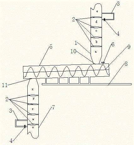
[0024] The continuous autoclaving device of the present invention includes a pressure cylinder 5, and also includes a vertical cylinder-shaped feed bin 1 and a discharge bin 7 respectively. 1 There is a feed port 10 at the corresponding position, and the lower part of the feed bin 1 is connected with the pressure cylinder 5 through the feed port 10; 5 There is a discharge port 11 at the position corresponding to the discharge bin 7, and the upper part of the discharge bin 7 is connected with the pressure cylinder 5 through the discharge port 11;

[0025] There is an auger 9 inside the pressure cylinder 5 as a pushing device, which continuously stirs, turns and pushes the material released from the feed bin 1 to the pressure cylinder 5, and improves the steam pressure efficiency of the material.

[0026] There are four valve bodies 2 in the feed bin 1 and the discharge bin 7, and the 4 valve bodies 2 in the feed bin 1 are arranged in order from top to bottom. The valve body 2 c...

Embodiment 2

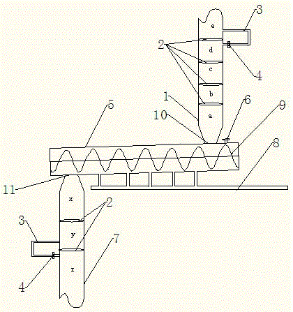
[0039] The difference from Embodiment 1 is that the discharge bin is set as three bin units of x, y, and z, and its operation principle is the same as that of Embodiment 1.


PUM


Abstract

The invention belongs to the field of chemical engineering equipment, particularly relates to a continuous steam pressing device, and further relates to a continuous steam pressing method using the continuous steam pressing device. The continuous steam pressing device comprises a pressure cylinder, and further comprises a feed bin and a discharge bin, wherein the lower part of the feed bin is connected with one end of the pressure cylinder; the discharge bin is connected with the other end of the pressure cylinder; a push device is arranged in the pressure cylinder; the pressure cylinder communicates with a pressure supply device; multiple valve bodies are arranged in each of the feed bin and the discharge bin; and materials are conveyed among multiple units of the bins in a free falling mode through the gravity condition. The multiple valve bodies are arranged in the feed bin and the discharge bin for realizing isobaric transfer of the materials in the feed bin and the discharge bin; and the valve bodies in the bins are used for controlling the pressure balance in the feed bin, the discharge bin and the pressure cylinder to realize continuous pressurization, steam pressing and pressure relief processes in the steam pressing process, so that the production efficiency and the energy utilization rate are improved.

Description

technical field [0001] The invention belongs to the field of chemical equipment, specifically relates to a continuous autoclaving device, and also relates to a continuous autoclaving method using the above-mentioned continuous autoclaving device. Background technique [0002] The existing autoclaving device generally includes a pressure cylinder and a cover at both ends of the pressure cylinder. When feeding is required, open the cover at one end, put the material into the pressure cylinder, and then autoclave. Pressure relief, because the pressure relief time is long, and continuous production cannot be performed during the pressure relief process, resulting in low efficiency, especially for materials with a long reaction time, which seriously affects the normal operation of other processes and significantly reduces production efficiency, and the above-mentioned The discontinuous autoclaving device basically releases the pressure in the autoclaving device due to its intermi...

Claims


Application Information

Patent Timeline
Patent Type & Authority Patents(China)
IPC IPC(8): B65G49/00B65G47/18B65G47/44B65G33/14
Inventor 丁方军陈士更孟庆羽吴钦泉马学文陈卫民张宏林胜勇
Owner SHANDONG AGRI UNIV FERTILIZER TECH CO LTD
Learn More