Display panel and display device
A technology for display panels and display devices, which is applied to identification devices, instruments, etc., can solve the problems of complex process steps and high cost, and achieve the effects of simple process, low production cost, and improved user experience.
- Summary
- Abstract
- Description
- Claims
- Application Information
AI Technical Summary
Problems solved by technology
Method used
Image
Examples
Embodiment 1
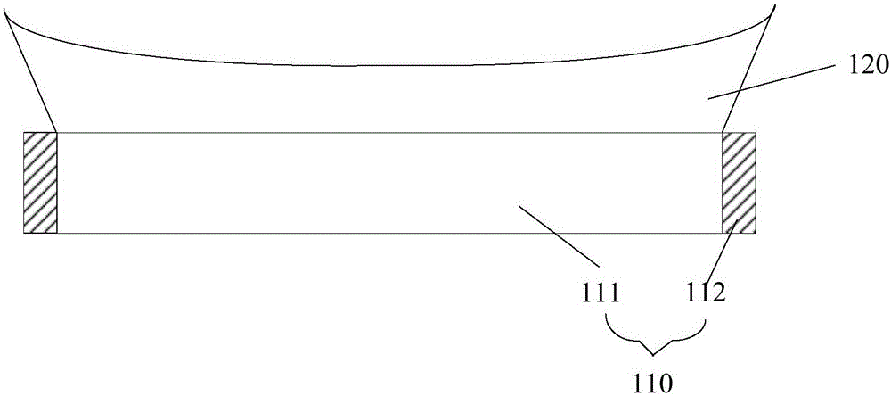
[0026] figure 1 A schematic structural diagram of a display panel provided in Embodiment 1 of the present invention, as shown in figure 1 As shown, the display panel includes:
[0027] A display substrate 110, including a display area 111 and a frame area 112 surrounding the display area;
[0028] The concave body 120 is located above the light emitting side of the display substrate 110 and is used to change the direction of light emitted from the display area 111 so that the image displayed on the display area 111 covers the frame area 112 .
[0029] It should be noted, figure 1 The frame area 112 is set on the left and right sides of the display area in an exemplary manner, but is not limiting to the present invention. For example, the frame area can also be set around the display area.
[0030] Further, the concave body 120 is a transparent material with a refractive index of 1.5-1.9, for example, glass, polymethyl methacrylate, polycarbonate, methyl styrene, cycloolefin...
Embodiment 2
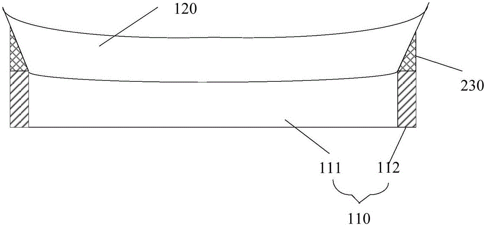
[0037] figure 2 It is a schematic structural diagram of another display panel provided by Embodiment 2 of the present invention.
[0038] Such as figure 2 As shown, in the display panel, the light-emitting side of the display area 111 of the display substrate 110 is a concave surface with a preset curvature, and the lower surface of the concave body 120 located above the display area 111 is set as a corresponding convex surface, so that the concave surface body 120 and the display area 111 can achieve seamless bonding.
[0039] Preferably, the display panel described in this embodiment may further include a fixing strip 230, located between the side of the concave body 120 and the frame area 112 of the display substrate 110, for connecting the concave body 120 and the The display substrate 110 is described above. Specifically, optical glue or other adhesives can be used to bond the sides of the fixing strip 230 to the side of the concave body 120 , and the bottom surface ...
Embodiment 3
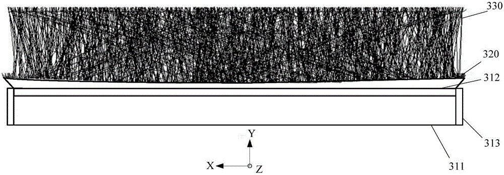
[0041] image 3 The light simulation diagram of the display panel provided by Embodiment 3 of the present invention. Such as image 3 As shown, the display panel simulated by the optical modeling software LightTools includes, from bottom to top, a backlight 311 of the display panel, a display area 312 of the display substrate, a border area 313 and a concave body 320 . Wherein, the light emitting side of the display area 312 is a plane, the lower surface of the concave body 320 is a plane, and the upper surface is a concave surface.
[0042] At the parts near the frame area 313 on both sides of the display area 312 , the light 330 emitted from the backlight 311 diverges outward, which means that the image seen from the upper surface of the concave body 320 can cover the frame area 313 . Therefore, the display panel in this embodiment can not only realize the effect of borderless display, but also realize the effect of curved screen display.
[0043] Figure 4 The luminance...
PUM
 Abstract
Description
Claims
Application Information
 - R&D
- Intellectual Property
- Life Sciences
- Materials
- Tech Scout
- Unparalleled Data Quality
- Higher Quality Content
- 60% Fewer Hallucinations
Browse by: Latest US Patents, China's latest patents, Technical Efficacy Thesaurus, Application Domain, Technology Topic, Popular Technical Reports.
© 2025 PatSnap. All rights reserved.Legal|Privacy policy|Modern Slavery Act Transparency Statement|Sitemap|About US| Contact US: help@patsnap.com


