Cooling device component with control valve for electric well in building

A technology for cooling devices and power wells, which is applied to electrical components and other directions, can solve the problems of complex structure of cooling devices, safety risks of building electricity, and difficult heat dissipation of cooling devices, so as to avoid unstable factors, compact structure, and reduce local overheating areas. Effect

Inactive Publication Date: 2015-12-09
王启先
View PDF5 Cites 0 Cited by
  • Summary
  • Abstract
  • Description
  • Claims
  • Application Information

AI Technical Summary

Problems solved by technology

This uneven heat build-up has a damaging effect on the insulation on the cable surface and poses a potential risk to the electrical safety of the entire building
[

Method used


Image

  • Cooling device component with control valve for electric well in building
  • Cooling device component with control valve for electric well in building

Examples


Example Embodiment

[0011] Combine below Figure 1-2 The present invention will be described in detail.

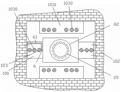
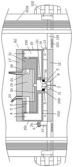
[0012] According to an embodiment, a cooling device assembly for a power well in a building with a control valve includes a plurality of cooling devices that are separately arranged along the vertical direction of the power well and are supplied with gas by a gas delivery pipe 61, and each cooling device It includes a cooling device body 82 and a fixing bracket 100 arranged on both sides of the cooling device body 82 for fixing on two opposite side walls 102 of the power well, and the fixing bracket 100 is provided with a power supply cable 1030 passes through the cable fixing hole 103, the cooling device body 82 includes an annular cavity housing 15 provided with a gas inlet nozzle 6 to communicate with the gas delivery pipe 61, and the gas inlet nozzle 6 is provided with A control valve 26 is used to control the gas supply volume of the gas inlet nozzle 6, the control valve 26 is an electr...


PUM


Abstract

The invention discloses a cooling device component with a control valve for an electric well in a building. The cooling device component comprises a plurality of cooling devices, wherein the plurality of cooling devices are separately arranged along the vertical direction of the electric well and are supplied with air by an air delivery pipe (61); each cooling device comprises a cooling device body (82) and fixed brackets (100); the fixed brackets (100) are arranged at two sides of the cooling device bodies (82) and are used for being fixed on two opposite side walls (102) of the electric well; cable fixing holes (103) through which power cables (1030) pass are formed in the fixed brackets (100); each cooling device body (82) comprises a ring cavity shell (15); the ring cavity shell (15) is provided with an air inlet pipe nozzle (6) to be communicated with the air delivery pipe (61); a control valve (26) is arranged on the air inlet pipe nozzle (6) for controlling the air supply amount of the air inlet pipe nozzle (6); and the control valve (26) is an electromagnetic control valve.

Description

technical field [0001] The application relates to the field of construction, in particular to a cooling device assembly for a power well in a building with a control valve. Background technique [0002] In the building, in order to uniformly supply power to the electrical equipment on each floor, a power well is often provided to allow power cables to pass between floors. In order to discharge the heat generated by the cables in the power well in time and ensure the safety of electricity use, the power well is usually provided with a common exhaust pipe to discharge the heat uniformly. [0003] During the long-term use of power cables, the power consumption of each floor is different, and the different structures that the cables pass through and the different changes in the quality of the cables will cause concentrated heat accumulation in the cable bundle. This uneven heat accumulation has a damaging effect on the insulation layer on the surface of the cable and poses a po...

Claims


Application Information

Patent Timeline
IPC IPC(8): H02G3/03
Inventor 王启先
Owner 王启先
Why Eureka
Try Eureka