Vehicle-mounted starting circuit and power supply compensating circuit thereof

A technology for power compensation and start-up circuits, which is applied to electrical components, control generators, control systems, etc., and can solve problems such as default value drift

Active Publication Date: 2015-12-09
UNIVERSAL SCIENTIFIC INDUSTRIAL (SHANGHAI) CO LTD
View PDF6 Cites 1 Cited by
  • Summary
  • Abstract
  • Description
  • Claims
  • Application Information

AI Technical Summary

Problems solved by technology

However, this method needs to set the default value based on experience, and the default value may drift, resulting in misjudgment

Method used


Image

  • Vehicle-mounted starting circuit and power supply compensating circuit thereof
  • Vehicle-mounted starting circuit and power supply compensating circuit thereof
  • Vehicle-mounted starting circuit and power supply compensating circuit thereof

Examples


Embodiment Construction

[0041] In the following, the structural elements and the achieved effects of the vehicle starting circuit and its power supply compensation circuit of the present invention will be described with reference to the accompanying drawings and corresponding preferred embodiments. However, the components and modules of the on-vehicle starting circuit and its power supply compensation circuit in each drawing are only used to illustrate the technical features of the present invention, not to limit the present invention.

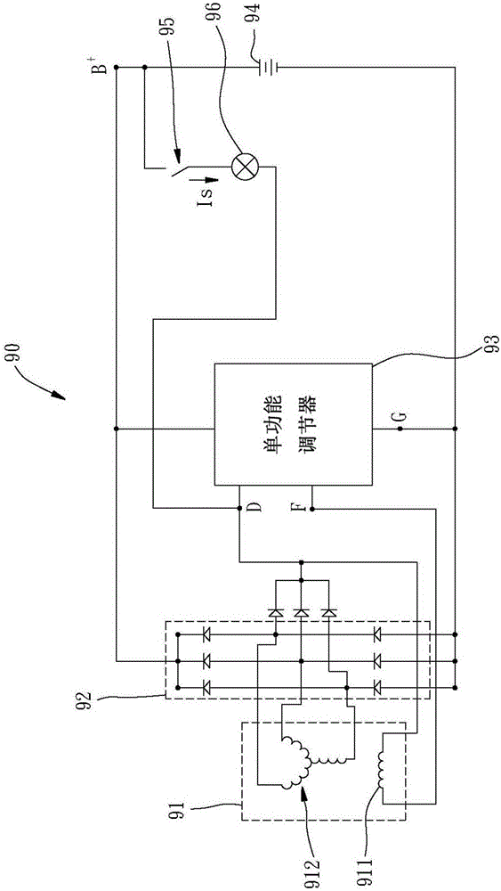
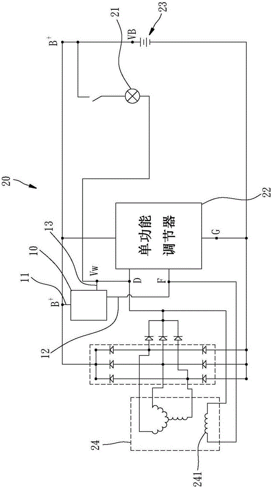
[0042] image 3 It is a schematic diagram that the power supply compensation circuit of the present invention is connected in the vehicle starting circuit. Such as image 3 As shown, the power supply compensation circuit 10 of the present invention is connected to the vehicle starting circuit 20 and is used to prevent the indicator light 21 of the vehicle starting circuit 20 from falsely starting. Wherein, the vehicle starting circuit 20 is roughly the same as the ...


PUM


Abstract

A power supply compensating circuit is connected to a vehicle-mounted starting circuit and comprises a first input end, a second input end and an output end. The first input end is used for detecting the battery voltage level of the vehicle-mounted starting circuit; the second input end is connected with a rotor of a power generator of the vehicle-mounted starting circuit; and when the battery voltage level is equal to or larger than load rejection voltage level, the power supply compensating circuit compensates for the voltage level of the output end to enable the voltage level of the output end to be maintained to be a working level in the compensating time, wherein the working level is the voltage level for enabling an indicator light of the vehicle-mounted starting circuit to be off. Therefore, the power supply compensating circuit can prevent misoperation of the indicator light in the vehicle operation process.

Description

technical field [0001] The invention relates to a vehicle starting circuit, in particular to a power compensation circuit and a vehicle starting circuit using the power compensation circuit. Background technique [0002] Such as figure 1 As shown, the conventional vehicle starting circuit 90 includes an alternator 91 , a rectifier 92 , a single-function regulator 93 , a battery 94 , an ignition switch 95 and a warning lamp 96 . [0003] The generator 91 has a rotor (rotor) 911 and a stator (stator) 912, and the rotor 911 and the stator 912 have field windings, respectively. Rectifier 92 with Node B + , node D and node G are connected. Node B + Corresponds to the positive terminal of the battery 94 . Node D is the common junction of the rectifier 92 , the single-function regulator 93 , the indicator light 96 and the rotor 911 . Node G corresponds to the ground reference point of the conventional on-board starting circuit 90 and is connected to the rectifier 92 , the sin...

Claims


Application Information

Patent Timeline
Patent Type & Authority Applications(China)
IPC IPC(8): H02P9/08H02P101/45
Inventor 吴信鸿
Owner UNIVERSAL SCIENTIFIC INDUSTRIAL (SHANGHAI) CO LTD
Why Eureka
Try Eureka