
Sight positioning device

A positioning device and line-of-sight technology, applied in the field of line-of-sight tracking, can solve the problems of few 3D features and the inability to achieve line-of-sight positioning, and achieve the effect of high-precision line-of-sight positioning

Active Publication Date: 2015-12-09
SHENZHEN INST OF ADVANCED TECH
View PDF7 Cites 23 Cited by
  • Summary
  • Abstract
  • Description
  • Claims
  • Application Information

AI Technical Summary

Problems solved by technology

Compared with 2D tracking technology, the accuracy and stability have been improved. The main problem is that there are relatively few 3D features available, and only a few feature points can be used to obtain the approximate 3D motion information of the eyeball, but it is impossible to achieve high-precision line of sight positioning.

Method used


Image

  • Sight positioning device
  • Sight positioning device
  • Sight positioning device

Examples


Embodiment Construction

[0026] In order to make the object, technical solution and advantages of the present invention clearer, the present invention will be described in further detail below in conjunction with the embodiments and accompanying drawings. Here, the exemplary embodiments and descriptions of the present invention are used to explain the present invention, but not to limit the present invention.

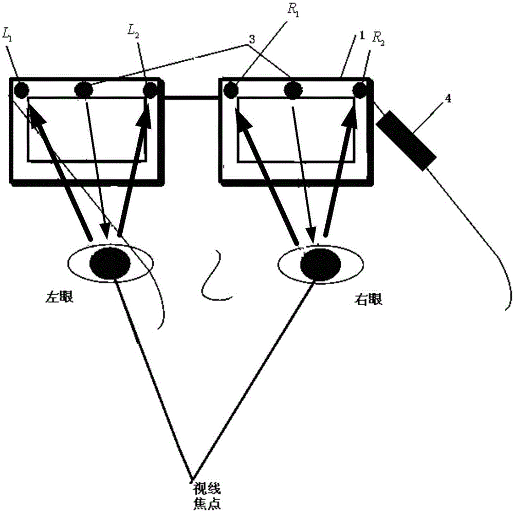
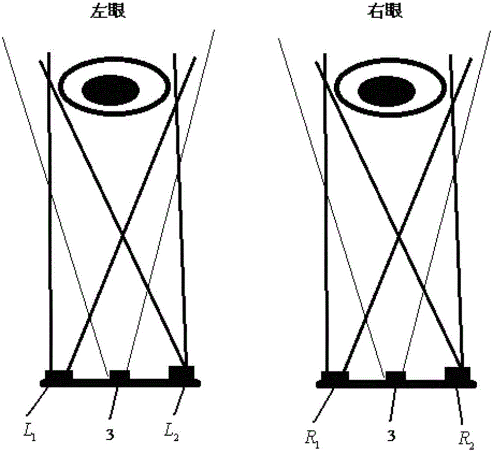
[0027] In an embodiment of the present invention, a line-of-sight positioning device is provided, such as figure 1 As shown (taking four cameras as an example, two cameras L1 and L2) take eye movement images of the left eye, two cameras R1 and R2 take eye movement images of the right eye, and 4 is a signal processing module, for example, the signal processing Module can include image processing equipment, iris three-dimensional reconstruction equipment and line of sight positioning equipment, etc.), and this line of sight positioning device includes:

[0028] At least four cameras, at least tw...


PUM

PropertyMeasurementUnit
Wavelengthaaaaaaaaaa

Abstract

An embodiment of the invention provides a sight positioning device. The device comprises at least four cameras, an image processing device, and an iris three-dimensional reconstruction device. At least two of the at least four cameras are used for separately taking eyeball motion photos of a left eye at different angles in real time, and at least two of the at least four cameras are used for separately taking eyeball motion photos of a right eye at different angles in real time. The at least four cameras take photos synchronously. The image processing device is used for determining a pupil position and an iris edge in each eyeball motion photo. The iris three-dimensional reconstruction device reconstructs according to the positions of the at least two cameras photographing the left eye and the pupil position and iris edge of the left eye in the eyeball motion photos taken by the at least two cameras so as to obtain a three-dimensional left eye iris edge, determines the central point and sight direction of the left eye iris in the three-dimensional space, and determines the central point and sight direction of the right eye iris in the three-dimensional space. In world coordinates, the sight positioning device determines the focus of the sight direction of the left eye iris and the sight direction of the right eye iris to be a sight focus. The sight positioning device can realize high precision sight positioning.

Description

technical field [0001] The invention relates to the technical field of sight tracking, in particular to a sight positioning device. Background technique [0002] Humans obtain a lot of information through the eyes, and at the same time use the eyes to express emotions and ideas. By tracking the focus of sight, people can obtain rich information from the eyes, and then carry out effective human-computer interaction and research in communication, psychology and other fields. [0003] Gaze tracking is the process of using various detection methods to obtain the "gaze point" and ensure that it can be continuously tracked for a period of time. This technology is widely used in human-computer interaction, virtual reality and other fields. Nowadays, there are many similar devices for eye-tracking. For example, an operation pointer indication control device based on human eye images and eye-tracking, which can be worn on the human head and can operate and control the operation poi...

Claims


Application Information

Patent Timeline
IPC IPC(8): H04N13/00G06T7/00G06T17/00G06K9/00
Inventor 宋展郑智航岳恒
Owner SHENZHEN INST OF ADVANCED TECH
Learn More