Eureka AIR delivers breakthrough ideas for toughest innovation challenges, trusted by R&D personnel around the world.

Foam type soap dispenser

A soap dispenser and foam-type technology, which is applied in the field of soap dispensers, can solve the problems of unstable foam volume, different sizes of foam bubbles, and less foam volume, and achieve stable foam volume, controllable foam volume, and rich foam delicate effect

Active Publication Date: 2015-12-16
台山市捷达电器有限公司
View PDF5 Cites 9 Cited by
  • Summary
  • Abstract
  • Description
  • Claims
  • Application Information

AI Technical Summary

Problems solved by technology

The common foam soap dispensers on the market today generally have these two types: one is to install a piston assembly behind the grid or mesh barrier, and the piston assembly moves to mix air and liquid and output it to the outside of the net. This kind of mixing action plus mesh division produces foam, but the amount of foam is small, and the piston assembly is easy to get stuck and has a short life; the other is to use a combination of screws and sleeves to extract liquid and deliver it to a simple In the gear pump, the gears in the gear pump rotate to mix the air and the liquid to produce foam. However, the foam soap produced by this method has different bubble sizes and is very uneven. In this way, the liquid outlet speed will be slowed down because the soap liquid is blocked, and the foam is easy to discharge and drip from the pores, and the screw pumping device is also easy to allow the liquid to flow back, prolonging the speed of the second pumping liquid, resulting in foam volume. Unstable; plus components get stuck easily, have a short lifespan, and are prone to leaks

Method used


Image

  • Foam type soap dispenser
  • Foam type soap dispenser
  • Foam type soap dispenser

Examples


Embodiment Construction

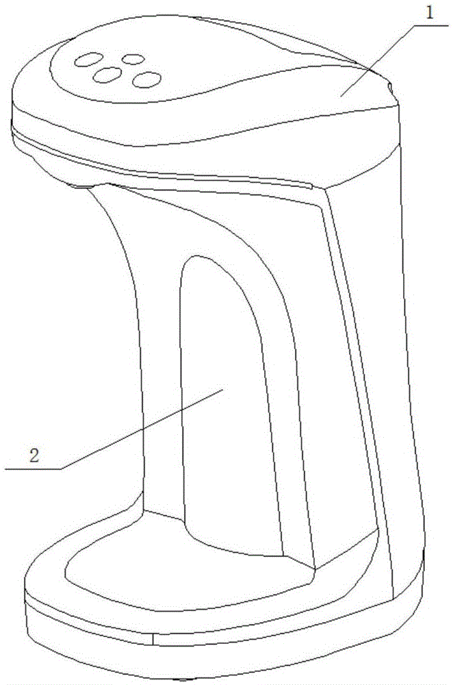
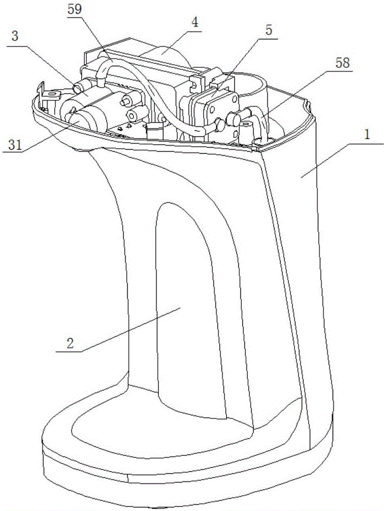
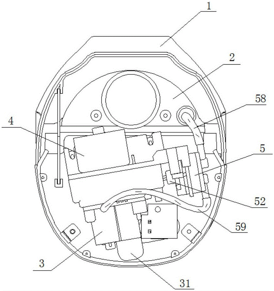
[0023] Such as Figure 1-Figure 11 As shown, the present invention discloses a foam type soap dispenser, which includes a housing 1 , and a liquid storage bottle 2 , an induction control device, a power device, an extracting device and a foam making device 3 arranged in the housing 1 .

[0024] The extraction device includes a pressure pump 5 with a liquid inlet A and a liquid outlet B. The foam making device 3 includes a one-way air inlet 35 and a foam chamber 34 with a nozzle 31. The liquid inlet of the pressure pump 5 A is communicated with the liquid output port of the liquid storage bottle 2, and the liquid outlet B of the pressure pump 5 is communicated with the foam-making cavity. A toothed screw shaft 32 and a smooth screw shaft 33 are arranged in the foam-making cavity 34. The toothed screw shaft 32 and the pressure pump 5 are respectively connected with a power device, and the power device provides power for the toothed screw shaft 32 and the pressure pump 5 . The p...


PUM


Abstract

The invention discloses a foam type soap dispenser. The foam type soap dispenser comprises a shell. A liquid storage bottle is arranged on the shell. An induction control device, a power device, an extraction device and a foam making device are further arranged on the shell. The extraction device comprises a pressure pump with a liquid inlet and a liquid outlet. The foam making device comprises a one-way air inlet and a foam making cavity with a spray nozzle. The liquid inlet of the pressure pump is communicated with the liquid storage bottle. The liquid outlet of the pressure pump is communicated with the foam making cavity. A toothed spiral shaft and a polished spiral shaft are arranged in the foam making cavity. The toothed spiral shaft and the pressure pump are connected with the power device and powered by the power device. A method that the two spiral shafts are combined for work to mix air and liquid is adopted, made foam is rich and fine, the amount of the foam is stable, foam soap liquid with different air contents and the foam output can be generated through control over the rotating speeds of the spiral shafts, and therefore the output foam quality and the foam output are controllable.

Description

technical field [0001] The invention relates to a soap dispenser. Background technique [0002] A soap dispenser is a device that can squeeze and output soap liquid for people to clean their hands and faces. It usually includes a liquid storage bottle or a liquid storage pool for storing soap liquid, and an extraction device with a nozzle for extracting the soap liquid is arranged on the liquid storage bottle or liquid storage pool. However, the old-fashioned soap dispenser that can only simply output soap liquid can no longer satisfy modern people's pursuit of a comfortable life. Therefore, the foam type soap dispenser that can make common soap liquid produce foam when outputting, becomes foam soap liquid arises at the historic moment. The common foam soap dispensers on the market today generally have these two types: one is to install a piston assembly behind the grid or mesh barrier, and the piston assembly moves to mix air and liquid and output it to the outside of the...

Claims


Application Information

Patent Timeline
IPC IPC(8): A47K5/122
Inventor 伍启生黄瑞科伍锐龙曾楠
Owner 台山市捷达电器有限公司
Why Eureka
Eureka Blog
Learn More