
Novel propelling mechanism for double bookbinding machines

A technology of a propulsion mechanism and a binding machine, applied in binding and other directions, can solve problems such as unguaranteed, affecting the appearance of documents, affecting the quality of binding, etc., and achieve the effect of beautiful binding

Active Publication Date: 2015-12-16
NANTONG YOUYUAN ART PATTERN DESIGN CO LTD
View PDF5 Cites 16 Cited by
  • Summary
  • Abstract
  • Description
  • Claims
  • Application Information

AI Technical Summary

Benefits of technology

This patented technology describes a novel way to attach tools onto sheets of material securely without damaging it during printing processes. It uses special machines called twin binders instead of traditional methods like staples. These twins have guiding parts attached to their back ends, allowing they move smoothly through narrow openings within the sheet's materials being printed. They also include movable platforms where both stationary and mobile seates connect to each tool holder. Each arm has its own movement system controlled by another part of the device itself. By controlling these movements, the chains inside the devices allow precise control over how tighten up certain portions of the pages when joined together.

Problems solved by technology

This technical problem addressed in this patented text relates to improving the accuracy and efficiency when securing documents together through bindings made up from traditional methods like staples or glue guns. Current solutions require manual adjustment during assembly due to lack of an accurate location reference system. Additionally, current systems have difficulty controlling how well each hole fits onto the edges of the sheet being secured without causing any issues such as misalignments between different pages or poorly-fitted sheets.

Method used


Image

  • Novel propelling mechanism for double bookbinding machines
  • Novel propelling mechanism for double bookbinding machines
  • Novel propelling mechanism for double bookbinding machines

Examples


Embodiment Construction

[0025] The present invention will be further described in detail below in conjunction with the accompanying drawings and embodiments.

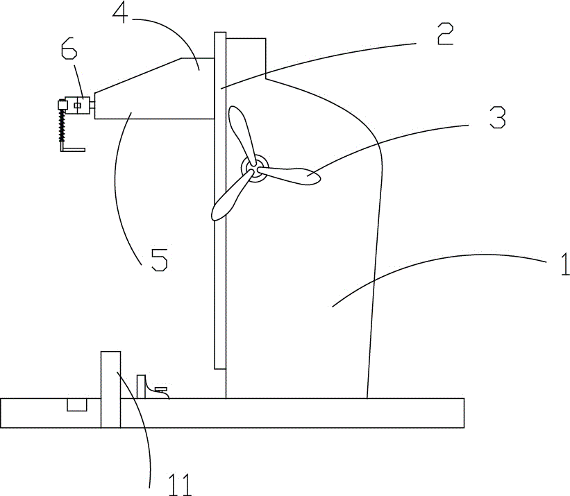
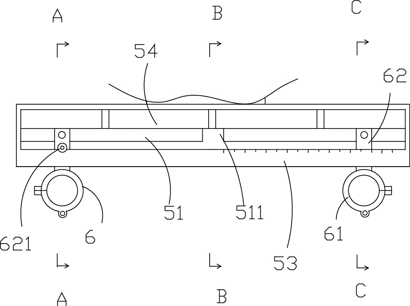
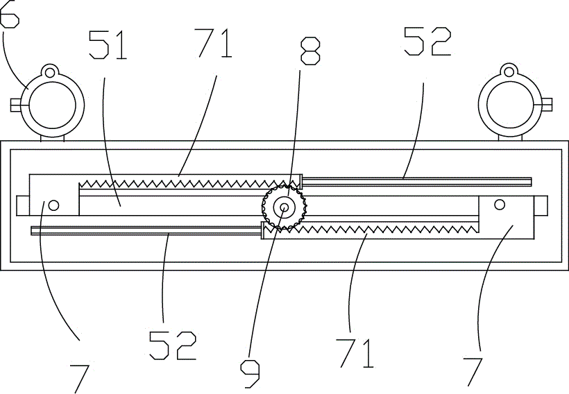
[0026] Such as Figure 1 to Figure 8 Shown is the structural representation of the present invention,

[0027] The reference signs therein are: bracket 1, guide 2, feed unit 3, propulsion unit 4, adjustment table 5, slotted hole 51, mounting beam 511, adjustment chuck 6, moving seat 7, rack 71, gear 8. Fastening screw 9, rib 52, flange body 81, lower cylinder 82, upper cylinder 83, bottom plate 10, lower installation part 101, upper installation part 512, clamper 61, strip-shaped horizontal plate 62, Front baffle 53 , rear baffle 54 , locking device 621 , positioning caliper 11 .

[0028] Such as Figure 1 to Figure 8 as shown,

[0029] A new type of double binding machine propulsion mechanism, including a bracket 1, a guide 2 is arranged on the bracket 1, a feed unit 3 can be operated automatically or manually through a rod, and a push un...


PUM


Abstract

The invention discloses a novel propelling mechanism for double bookbinding machines. The novel propelling mechanism comprises a bracket, wherein a guide part is arranged on the bracket; a feeding unit can automatically operate or can manually operate a propelling unit by virtue of a rod part to lift and shift along the guide part; a regulating table is arranged at the front end of the propelling unit; a long slot hole is transversely formed in the regulating table; a mounting beam is arranged on the center of the long slot hole; regulating chucks, which can relatively slide along the long slot hole and are symmetrically arranged relative to a longitudinal center line of the regulating table for locking a drilling machine, are arranged on the upper surface of the regulating table; two movable bases connected with the two regulating chucks are respectively arranged on the lower surface of the regulating table; each of the two movable bases is connected with a rack; a rotatable gear is arranged between the two movable bases; the two racks are respectively engaged with two sides of the gear; a fastening bolt is arranged on the gear in a penetration mode, and is fixedly connected with a mounting beam. Positions of bookbinding holes can be regulated according to the dimension of paper, so that the bookbinding is attractive.

Description


Claims


Application Information

Patent Timeline
Owner NANTONG YOUYUAN ART PATTERN DESIGN CO LTD
Learn More