Automatic welding machine for chains

An automatic welding machine and chain technology, applied in welding accessories, welding equipment, welding equipment, etc., can solve the problems of non-uniform weld size of welded parts, failure to meet production capacity requirements, and impact on the quality of the entire chain, so as to improve welding efficiency, Ensure the assembly accuracy and quality, and the welding seam is uniform, beautiful and firm.

Active Publication Date: 2014-03-19
ANHUI JIXI HUISHAN CHAIN TRANSMISSION +1
View PDF6 Cites 8 Cited by
  • Summary
  • Abstract
  • Description
  • Claims
  • Application Information

AI Technical Summary

Problems solved by technology

[0002] In the chain industry, the connection between the chain plate and the sleeve of the bent plate chain needs to be completed by welding. The coaxiality requirements between the sleeve hole and the chain plate hole are relatively high. If the welding error is too large, it will not only affect the pin shaft. Assembly, and will have an impact on the quality of the entire chain, resulting in unqualified products. If welding operations are performed manually, relatively large errors will inevitably occur, and the weld size of each weldment is not uniform, which is prone to Defects such as pores, slag inclusions, and false welds are very prone to such problems due to mental fatigue caused by repetitive work, and repetitive work is labor-intensive, time-consuming, labor-intensive, poor welding quality, and low welding efficiency. Production capacity requirements and poor economic benefits; and manual welding will inevitably inhale a large amount of gas generated during welding. Over time, it will cause great harm to the human body and pose a safety hazard

Method used


Image

  • Automatic welding machine for chains
  • Automatic welding machine for chains
  • Automatic welding machine for chains

Examples


Embodiment Construction

[0022] The following is a detailed description of the embodiments of the present invention. This embodiment is implemented on the premise of the technical solution of the present invention, and detailed implementation methods and specific operating procedures are provided, but the protection scope of the present invention is not limited to the following implementation example.

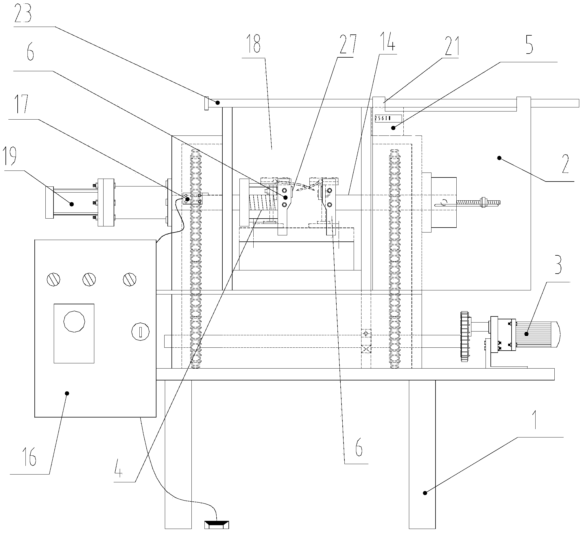
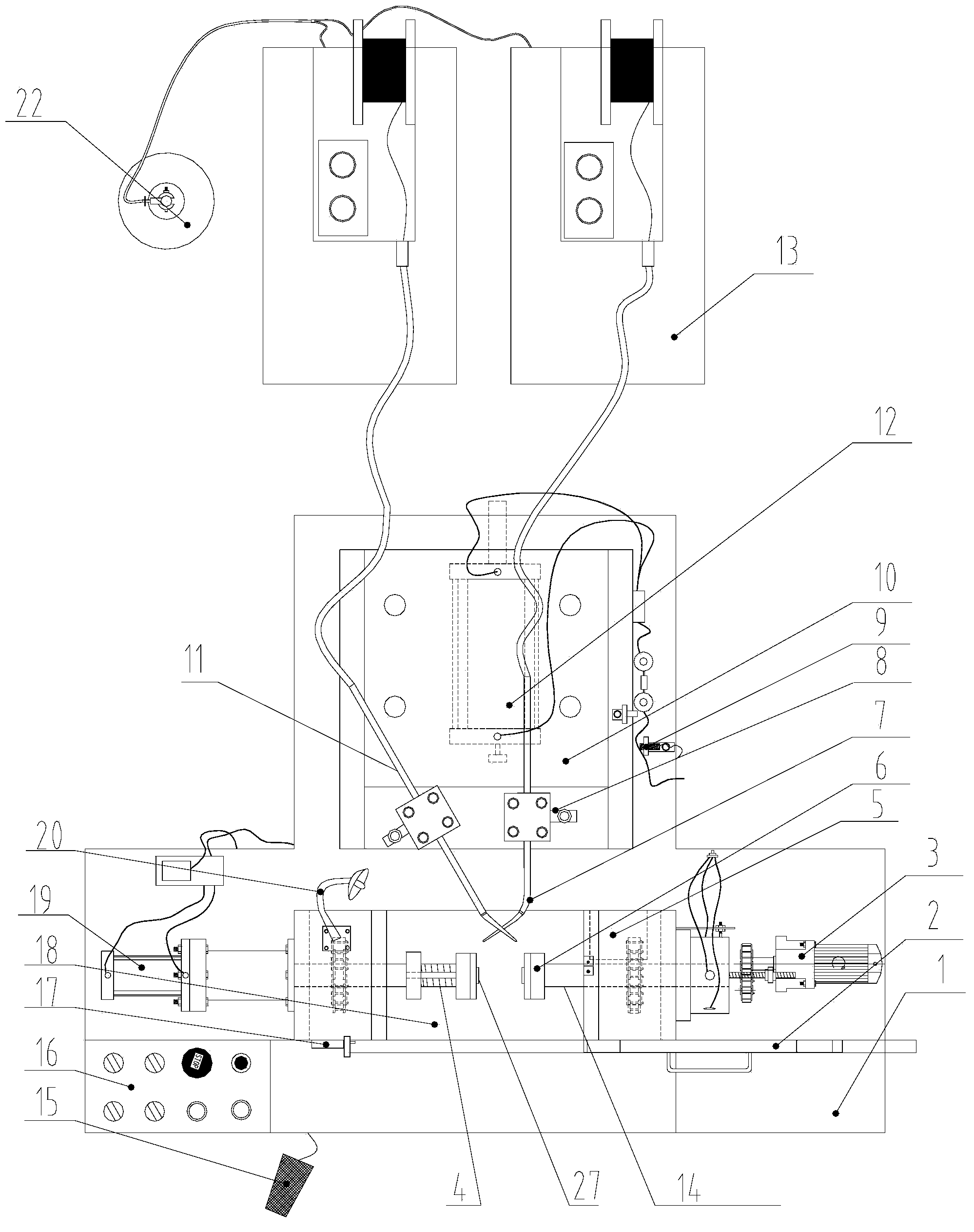
[0023] see figure 1 , figure 2 with Figure 4 , the chain automatic welding machine that present embodiment provides, comprises frame 1, is provided with positioning clamping system, transmission system, welding system and electric control system on frame 1, and positioning clamping system comprises clamping cylinder 19, the first rotation Rod 4 and the second rotating rod 14, the first rotating rod 4 and the second rotating rod 14 are coaxially arranged oppositely in the left and right directions, and a section area opposite to the first rotating rod 4 and the second rotating rod 14 forms a welding...


PUM


Abstract

The invention discloses an automatic welding machine for chains. The automatic welding machine comprises a rack, and a location clamping system, a transmission system, a welding system and an electronic control system are arranged on the rack. The location clamping system comprises a clamping air cylinder, a first rotation rod and a second rotation rod. The first rotation rod and the second rotation rod are arranged left and right coaxially and oppositely, a clamping plate is arranged at the opposite ends of the second rotation rod and the first rotation rod respectively, coaxial location columns extending inwards are arranged on the two clamping plates respectively, and the first rotation rod is controlled by the clamping air cylinder to move laterally. The transmission system comprises a motor and a chain drive mechanism, and the first rotation rod and the second rotation rod are driven by the motor and the chain drive mechanism to rotate synchronously. The welding system comprises a welding machine, a welding gun, a welding gun support, a welding gun support moving platform and a welding air cylinder. The electronic control system comprises a sensor, a stroke controller and a counter. The automatic welding machine has the advantages of being simple and rapid to operate, low in labor intensity, high in working efficiency, safe and reliable and good in welding quality.

Description

technical field [0001] The invention relates to the technical field of chain welding, in particular to an automatic chain welding machine. Background technique [0002] In the chain industry, the connection between the chain plate and the sleeve of the bent plate chain needs to be completed by welding. The coaxiality requirements between the sleeve hole and the chain plate hole are relatively high. If the welding error is too large, it will not only affect the pin shaft. Assembly, and will have an impact on the quality of the entire chain, resulting in unqualified products. If welding operations are performed manually, relatively large errors will inevitably occur, and the weld size of each weldment is not uniform, which is prone to Defects such as pores, slag inclusions, and false welds are very prone to such problems due to mental fatigue caused by repetitive work, and repetitive work is labor-intensive, time-consuming, labor-intensive, poor welding quality, and low weldin...

Claims


Application Information

Patent Timeline
Patent Type & Authority Applications(China)
IPC IPC(8): B23K37/02B23K37/047
CPCB23K9/12B23K9/16B23K9/32B23K37/0252B23K37/0435B23K37/047B23K2101/30
Inventor 沈继杰叶志华方建国张炜胡彬
Owner ANHUI JIXI HUISHAN CHAIN TRANSMISSION
Why Eureka
Try Eureka