Prefabricated tube pile embankment structure and construction method thereof

A technology for prefabricated pipe piles and pavement structures, applied in infrastructure engineering, roads, roads, etc., can solve problems such as limiting the scope of application of the replacement method, uneven grouting pressure, and pavement waves. The effect of preventing post-construction settlement and reducing the upper load

Inactive Publication Date: 2014-05-07
JIANGSU ZHONGRUI ROAD & BRIDGE CONSTR
View PDF6 Cites 26 Cited by
  • Summary
  • Abstract
  • Description
  • Claims
  • Application Information

AI Technical Summary

Problems solved by technology

Although this method can improve the bearing capacity of the weak soil layer to a certain extent and is convenient for construction, the maximum effective treatment depth of the replacement method is not more than 5m, which greatly limits the scope of application of the replacement method.
The grouting method is to use the grouting pipe to pour an appropriate amount of cement slurry into the soft soil area to be reinforced, and improve the bearing capacity of the subgrade by curing the soft soil layer; In areas with deep soil layers, it is difficult to pour cement grout into deep soft soil layers for grouting and solidification to improve bearing capacity. At the same time, improper control of grouting pressure can easily lead to uneven grouting, resulting in waves on the road surface
[0005] In summary, although the existing embankment structure treatment measures can achieve good results under suitable engineering conditions, there are still some areas that need to be improved.

Method used


Image

  • Prefabricated tube pile embankment structure and construction method thereof
  • Prefabricated tube pile embankment structure and construction method thereof
  • Prefabricated tube pile embankment structure and construction method thereof

Examples


Embodiment Construction

[0036] The present invention will be described in further detail below with reference to the accompanying drawings and examples. The following examples are explanations of the present invention and are not limited to the following examples.

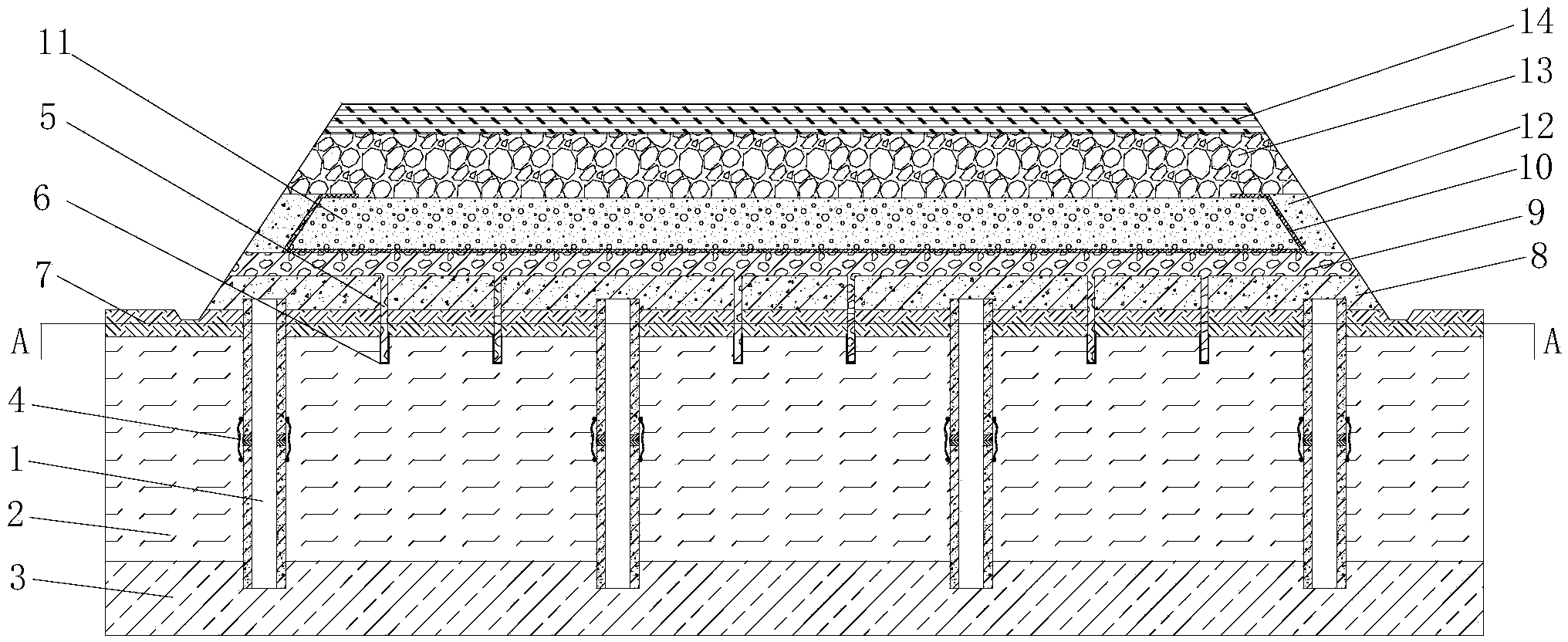
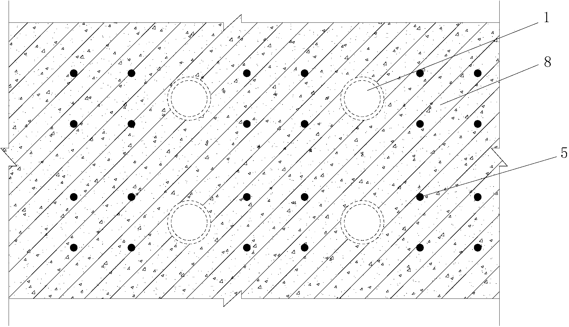
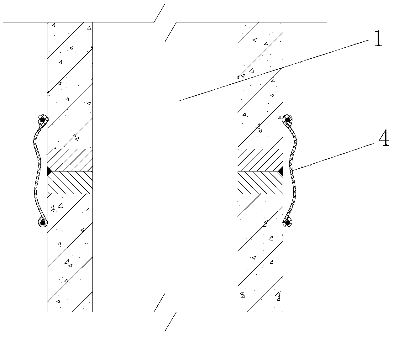
[0037] figure 1 It is the elevation view of the prefabricated tubular pile embankment structure of the present invention, figure 2 yes figure 1 Sectional view along line A-A. refer to Figure 1~2 As shown, the prefabricated pipe pile embankment structure is mainly composed of prefabricated pipe piles 1, vertical drainage pipes 5, shallow solidified slabs 7, thin reinforced concrete continuous slabs 8, crushed stone layers 9, filter geotextiles 10, air bubble concrete anti-rolling Layer 11, concrete protection layer 12, slag layer 13, pavement structure 14 and other parts.

[0038] Prefabricated pipe pile 1 adopts prefabricated pipe piles with a pile diameter of Φ400mm and a wall thickness of 90mm. The prefabricated pipe piles penetra...


PUM


Abstract

The invention relates to a prefabricated tube pile embankment structure, which mainly comprises a prefabricated tube pile, a vertical drain tube, a shallow curing plate, a thin reinforcement concrete continuous plate, a rubble layer, a bubble concrete rolling-resistant layer, a concrete protection layer, a slag layer and a pavement structure, wherein the prefabricated tube pile penetrates through a soft soil layer and extends a relative bearing stratum; a weld seam protection device is arranged outside a prefabricated tube pile welding end plate; the shallow curing plate is arranged at the periphery of the top of the prefabricated tube pile; the thin reinforcement concrete continuous plate is arranged on the shallow curing plate; the top of the prefabricated tube pile is embedded in the thin reinforcement concrete continuous plate; the vertical drain tubes are pre-buried in the thin reinforcement concrete continuous plate and the shallow curing plate, the lower ends of the vertical drain tubes are externally coated with a reverse filter geotextile which is communicated with the rubber layer on the thin reinforcement concrete continuous plate; the bubble concrete rolling-resistant layer, the slag layer and the pavement structure are sequentially arranged on the rubble layer. The prefabricated tube pile embankment structure is high in bearing capacity, less in differential settlement, high in overall structure stability, and convenient to construct.

Description

technical field [0001] The invention relates to a prefabricated tubular pile embankment structure and a construction method thereof, belonging to the field of roadbed engineering. The structure has the advantages of improving the bearing capacity of the roadbed and enhancing the stability of the roadbed, and is suitable for roadbed treatment projects in highways, railways and municipal roads in soft soil areas . Background technique [0002] In recent years, with the rapid and sustainable development of the economy in the Yangtze River Delta, the traffic flow has increased rapidly. In order to make the traffic capacity meet the needs of national economic and social development, the scale of road construction has increased day by day. Since the Yangtze River Delta is located in the coastal area of ​​my country, the coastal area is formed by silt deposits, and there is a wide range of soft soil layers. It has the characteristics of high natural water content, large void ratio,...

Claims


Application Information

Patent Timeline
Patent Type & Authority Applications(China)
IPC IPC(8): E01C3/00E01C3/04E02D3/10E02D27/12E02D27/14E02D31/00
Inventor 葛忠田向东徐辞剑叶国江巫东良
Owner JIANGSU ZHONGRUI ROAD & BRIDGE CONSTR
Why Eureka
Try Eureka