Ascending and descending fence

A fence and railing technology, applied in the field of fences, can solve problems such as height reduction, and achieve the effects of compact structure, reasonable design and strong practicability

Active Publication Date: 2015-12-16
ZHEJIANG UNITED CHANG TECH
View PDF9 Cites 8 Cited by
  • Summary
  • Abstract
  • Description
  • Claims
  • Application Information

AI Technical Summary

Problems solved by technology

[0002] Fences are widely used in all aspects of production and life. The height of existing fences is generally fixed after production. If the height does not meet the fence requirements at this time, such as the fence around the pasture, we need to heighten the fence to To prevent large animals from jumping over the fence and entering the pasture, it can only be operated by raising the overall height of the fence, and this process is irreversible. When the height of the fence exceeds the fence requirements, such as the outer fence of the pasture, we need to lower the fence When large animals can jump over the fence and enter the pasture, but small animals cannot jump over the fence and enter the pasture (the distance between the fence railings must also meet the requirements that small animals cannot pass), then it cannot be done without destroying its structure. height down

Method used


Image

  • Ascending and descending fence
  • Ascending and descending fence

Examples


Embodiment Construction

[0018] It should be noted that, in the case of no conflict, the embodiments of the present invention and the features in the embodiments can be combined with each other.

[0019] The present invention will be described in detail below with reference to the accompanying drawings and examples.

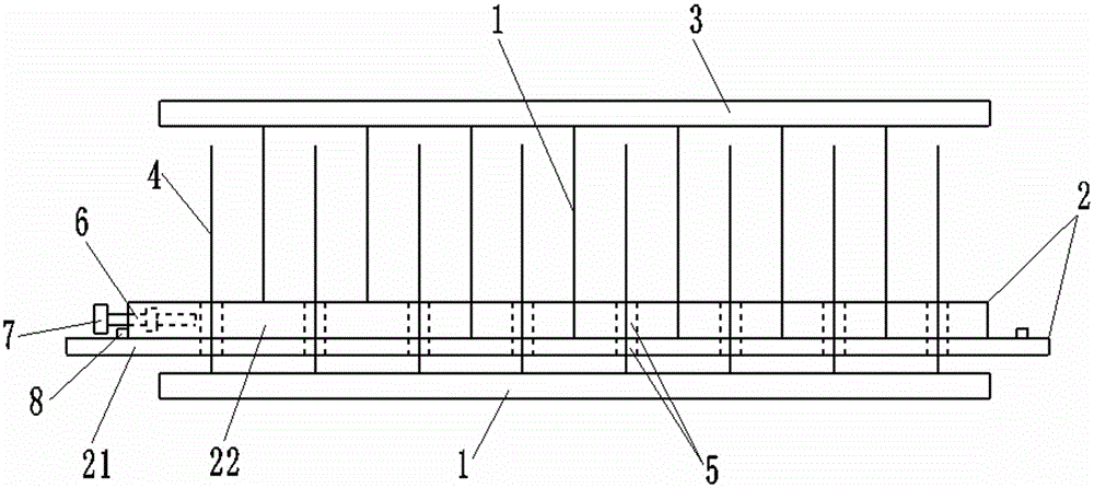
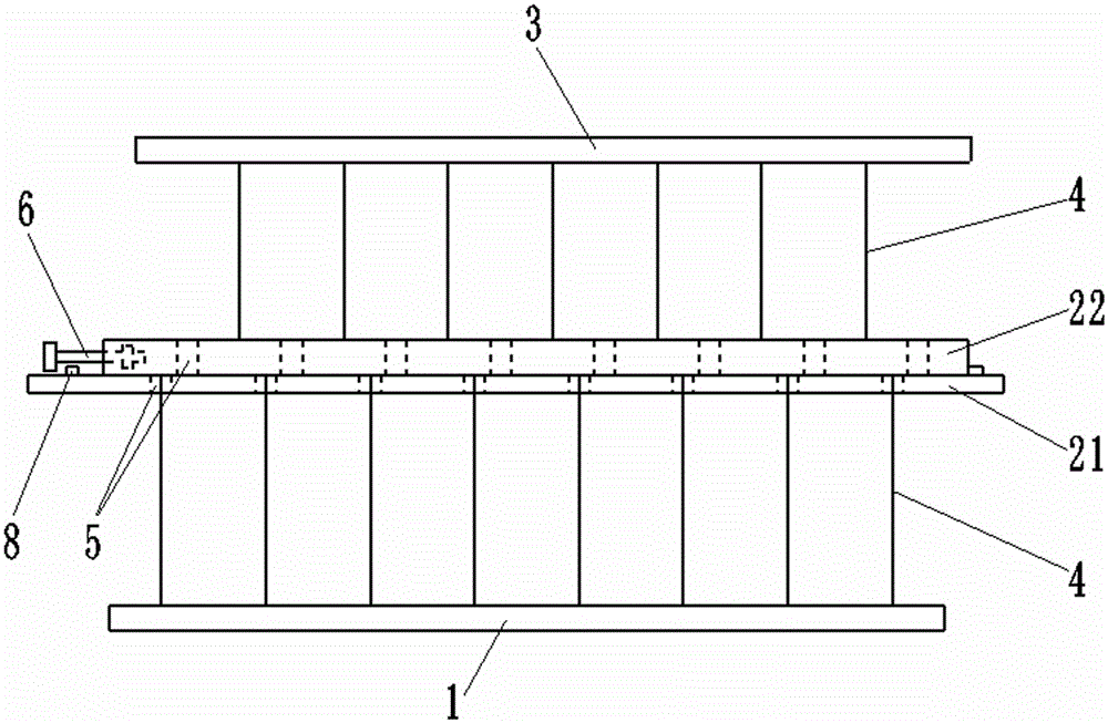
[0020] Lifting fence provided by the present invention, refer to figure 1 , 2 As shown, it includes a lower fence and an upper fence, the lower fence includes a lower rail bottom plate 1 and a railing 4 vertically fixed thereon, and the upper fence includes an upper rail bottom plate 2, an upper rail top plate 3 and a vertical distribution Between railings 4;

[0021] The upper hurdle bottom plate 2 is located on the lower hurdle bottom plate 1, the upper hurdle top plate 3 is higher than the height of the lower fence railing 4, the railings 4 of the lower fence and the upper fence are alternately arranged, and the upper hurdle bottom plate 2 includes components that can produce relati...


PUM


Abstract

The invention relates to an ascending and descending fence, which comprises an upper fence and a lower fence, wherein the lower fence comprises a lower fence bottom plate and handrails vertically fixed on the lower fence bottom plate; the upper fence comprises an upper fence bottom plate, an upper fence top plate and handrails vertically distributed between the upper fence bottom plate and the upper fence top plate; the upper fence bottom plate is positioned above the lower fence bottom plate; the upper fence top plate is higher than the handrails of the lower fence; the handrails of the upper fence and the handrails of the lower fence are alternately ranged; the upper fence bottom plate comprises an upper fence lower bottom plate and an upper fence upper bottom plate which can generate relative displacement in the length direction of the upper fence bottom plate; and through holes through which the handrails of the lower fence pass through are formed in the upper fence lower bottom plate and the upper fence upper bottom plate. According to the ascending and descending fence, when the high fence height is selected, the upper fence upper bottom plate is operated and controlled to move in the length direction of the upper fence upper bottom plate, so that the through holes of the upper fence upper bottom plate and the through holes of the upper fence lower bottom plate are staggered; and the upper end parts of the handrails of the lower fence are used for supporting the upper fence upper bottom plate, so that the upper fence bottom plate is prevented from falling. The ascending and descending fence has the advantages that the structure is compact; the design is reasonable; the switching between the high fence height and the low fence height can be conveniently realized according to practical requirements; and high practicability is realized.

Description

technical field [0001] The invention relates to a fence, in particular to a lifting fence capable of setting the height of the fence by "choosing one of the two" according to the specific environment where the fence is installed. Background technique [0002] Fences are widely used in all aspects of production and life. The height of existing fences is generally fixed after production. If the height does not meet the fence requirements at this time, such as the fence around the pasture, we need to heighten the fence to ensure To prevent large animals from jumping over the fence and entering the pasture, it can only be operated by raising the fence as a whole, and this process is irreversible. When the height of the fence exceeds the fence requirements, such as the outer fence of the pasture, we need to lower the fence When large animals can jump over the fence and enter the pasture, but small animals cannot jump over the fence and enter the pasture (the distance between the ...

Claims


Application Information

Patent Timeline
Patent Type & Authority Applications(China)
IPC IPC(8): E04H17/14
Inventor 郑文丽
Owner ZHEJIANG UNITED CHANG TECH
Why Eureka
Try Eureka