Connecting structure of pipe shell type heat exchanger pipe plate and heat exchange pipe

A heat exchanger and connection structure technology, which is applied in the field of connection structure between tube sheets and heat exchange tubes of shell-and-tube heat exchangers, can solve problems such as difficulty in ensuring connection strength and sealing between tube sheets and heat exchange tubes, and prevent Other failure modes, improving sealing performance, and ensuring the effect of sealing

Inactive Publication Date: 2015-12-16
LANZHOU LS GRP
View PDF5 Cites 1 Cited by
  • Summary
  • Abstract
  • Description
  • Claims
  • Application Information

AI Technical Summary

Problems solved by technology

[0004] The purpose of the present invention is to provide a connection structure between the tube sheet and the heat exchange tube of a shell-and-tube heat exchanger, so as to solve the problem that it is difficult to ensure the connection strength and tightness between the tube sheet and the heat exchange tube by means of expansion or welding. The problem

Method used


Image

  • Connecting structure of pipe shell type heat exchanger pipe plate and heat exchange pipe
  • Connecting structure of pipe shell type heat exchanger pipe plate and heat exchange pipe
  • Connecting structure of pipe shell type heat exchanger pipe plate and heat exchange pipe

Examples


Embodiment 1

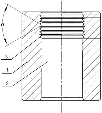
[0023] Such as figure 1 The connection structure between the tube plate and the heat exchange tube of a shell-and-tube heat exchanger shown includes a tube plate 1, a heat exchange tube hole 2 is provided on the tube plate 1, and a heat exchange tube hole 2 is provided on the inner wall of the heat exchange tube hole 2 There is a group of sealing groove group 3. The included angle α between the sides of two adjacent sealing grooves in the sealing groove group 3 is 30° to 60°. The sealing groove group 3 includes 3 to 12 sealing grooves.

Embodiment 2

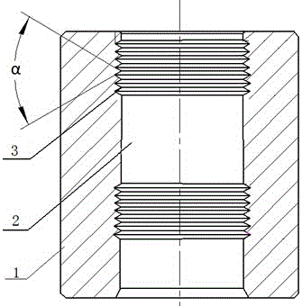
[0025] Such as figure 2 The connection structure between the tube plate and the heat exchange tube of a shell-and-tube heat exchanger shown includes a tube plate 1, a heat exchange tube hole 2 is provided on the tube plate 1, and a heat exchange tube hole 2 is provided on the inner wall of the heat exchange tube hole 2 There are two sets of seal groove sets 3 . The included angle α between the sides of two adjacent sealing grooves in the sealing groove group 3 is 30° to 60°. The sealing groove group 3 includes 3 to 12 sealing grooves.

[0026] In the present invention, at least one group of sealing grooves is arranged on the inner wall of the heat exchange tube hole on the tube plate, so that the connection mode between the tube plate and the heat exchange tube includes not only the expansion joint between the seal groove group and the outer wall of the heat exchange tube, but also includes The portion on the inner wall of the tube hole of the heat exchange tube that is not...


PUM


Abstract

The invention relates to the technical field of heat exchange equipment, and discloses a connecting structure of a pipe shell type heat exchanger pipe plate and a heat exchange pipe. The connecting structure comprises the pipe plate, wherein the pipe plate is provided with a heat exchange pipe hole; at least one sealing groove set is arranged on the inner wall of the heat exchange pipe hole; and the degree of the side edge included angle alpha of two adjacent sealing grooves in the sealing groove set ranges from 30 degrees to 60 degrees. The sealing groove set is arranged on the inner wall of the heat exchange pipe hole of the pipe plate, and the connecting manner between the pipe plate and the heat exchange pipe comprises expansion connection between the sealing groove set and the outer wall of the heat exchange pipe and face connection between the outer wall of the heat exchange pipe and the portion, without the sealing grooves, of the inner wall of the heat exchange pipe hole. The connecting manner of the heat exchange pipe and the pipe plate is changed into a linear sealing and face sealing combination manner from original face sealing; after the heat exchange pipe and the pipe plate are in expanded connection, defects like pores in welds cannot appear in the welding process of the heat exchange pipe and the pipe plate, and the sealing performance of the connecting position of the heat exchange pipe and the pipe plate is improved.

Description

technical field [0001] The invention relates to the technical field of heat exchange equipment, in particular to a connection structure between a tube sheet and a heat exchange tube of a shell-and-tube heat exchanger that is securely connected and not prone to leakage failure. Background technique [0002] In the shell-and-tube heat exchanger, the heat exchange tube and the tube sheet divide the heat exchanger into two independent pressure chambers on the tube side and the shell side, and the media will not mix. The heat exchange tubes are generally made of seamless steel pipes, and the tube sheets are processed by forgings. In actual use, the phenomenon of medium leakage and failure due to corrosion of the heat exchange tubes and tube sheets rarely occurs. The connection between the heat exchange tube and the tube sheet is the weakest part of the shell-and-tube heat exchanger, which is prone to gaps and medium leakage failures. Therefore, the connection structure and connec...

Claims


Application Information

Patent Timeline
Patent Type & Authority Applications(China)
IPC IPC(8): F28F9/18
Inventor 李治国周灵军张潮南安克鹏冯长林
Owner LANZHOU LS GRP
Why Eureka
Try Eureka