
Device for separating tubular web

A web and tubular technology, applied in the field of equipment for splitting tubular webs, can solve the problems of unreproducible pulling force, etc., and achieve the effect of improved production results, flexible and changeable settings

Inactive Publication Date: 2015-12-16
WINDMOELLER & HOELSCHER GMBH
View PDF7 Cites 0 Cited by
  • Summary
  • Abstract
  • Description
  • Claims
  • Application Information

AI Technical Summary

Problems solved by technology

Furthermore, it is disadvantageous in devices of this type that data storage is not possible order-by-order and that the desired pulling force cannot be reproduced

Method used


Image

  • Device for separating tubular web
  • Device for separating tubular web

Examples


Embodiment Construction

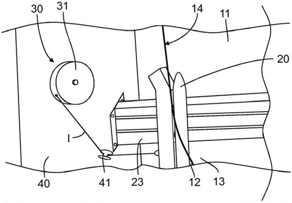
[0056] figure 1 A device for splitting the tubular web 11 into two flat webs 12, 13 is shown, as is known in the prior art. The device is equipped with an adjustable knife 20 which is aimed at the folded edge 14 of the tubular web 11 . The knife 20 is movable along a guide rail 23 which extends perpendicularly to the direction of travel of the tubular web 11 . As the tubular web 11 becomes wider, the knife 20 is moved to the left. As the tubular web 11 becomes narrower, the knife 20 is moved to the right in order to hit the fold 14 . to this end, figure 1 The device in is only designed so that the knife 20 is loaded towards the left in the view relative to the tubular web 11 towards the outside. The device here has a pulling device 30 with a rope drum 31 and a pulling rope I which is guided to the knife 20 via guide rollers 41 . Pull cord 1 keeps tension all the time and knife 20 is pressed to the left. However, there is the disadvantage that when unwinding and rewinding...


PUM


Abstract

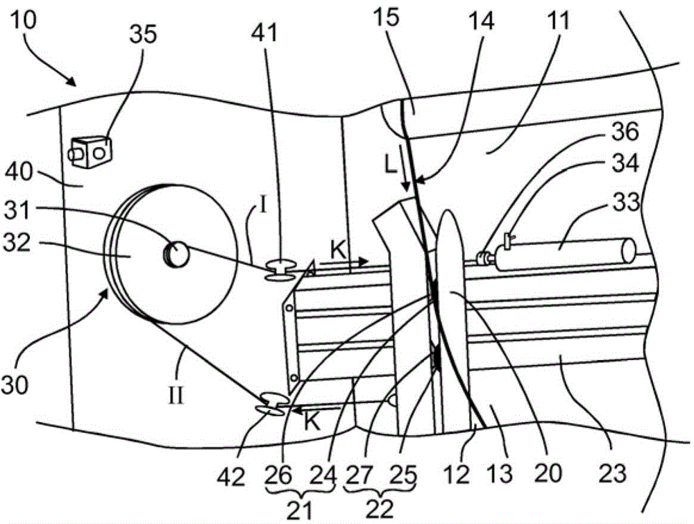
The invention relates to a device (10) for separating a tubular web (11) into two flat webs (12, 13), having an adjustable blade (20) for cutting the tubular web (11), and having a pulling device (30), which acts on the blade (20) applying a tensile force (K) on a folding edge (14) of the tubular web (11). The pulling device (30) is configured such that subject to the tube properties of the tubular web (11), the tensile force (K) can be adjusted, and that while the tube properties are constant, the tensile force (K) can essentially be held constant regardless of the tube width of the tubular web (11).

Description

technical field [0001] The invention relates to a device for dividing a tubular web into two flat webs. Background technique [0002] In the blowing process for producing tubular webs from plastic films, devices are known for dividing the tubular web into two flat webs. Here, the film is produced in the form of a tubular web and laid flat for transport. Here, two layers are formed which have to be split for further processing. Conventional devices for dividing tubular webs into flat webs have for this purpose adjustable knives which are aligned with the folded edges of the tubular web. Depending on the order, plastic films of different widths and properties are required, moreover, differences in tube widths and tube properties can arise during the course of the same order. In this case, it is necessary to apply a suitable pulling force to the knife for cutting a defined tubular web and to achieve a cut that is as straight as possible, regardless of the width of the tube. ...

Claims


Application Information

Patent Timeline
Patent Type & Authority Applications(China)
IPC IPC(8): B65H35/02B26D1/02B65B61/06
CPCB26D7/14B26D7/2628B65H35/02B65H2701/1752B26D1/025B26D1/035B26D3/001Y10T83/343Y10T83/386Y10T83/391Y10T83/6584Y10T83/73Y10T83/8776
Inventor 沃纳·柏根纳特
Owner WINDMOELLER & HOELSCHER GMBH
Learn More