
fuel injection system

A fuel injection system and fuel technology, applied in fuel injection pumps, fuel injection devices, fuel injection control, etc., can solve problems such as noise and achieve the effect of reducing torque peaks

Active Publication Date: 2019-10-01
VTESCO TECH GMBH
View PDF6 Cites 0 Cited by
  • Summary
  • Abstract
  • Description
  • Claims
  • Application Information

AI Technical Summary

Problems solved by technology

Furthermore, the periodic opening and closing of the inlet valve causes noise, the frequency of which is a function of the speed of the drive shaft of the high pressure pump

Method used


Image

  • fuel injection system
  • fuel injection system
  • fuel injection system

Examples


Embodiment Construction

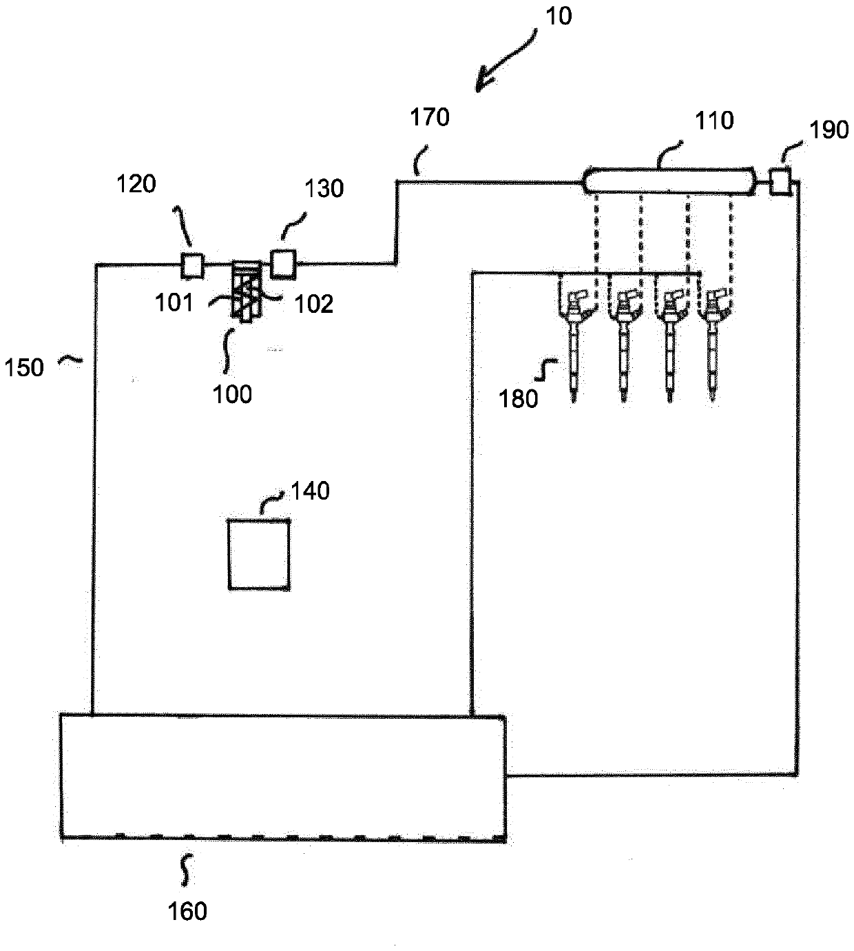
[0018] figure 1 An exemplary embodiment of a fuel injection system 10 is shown, which can be designed, for example, as a common rail fuel injection system. The fuel injection system includes a high-pressure pump 100 with a pump working space 101 for compressing fuel. The high-pressure pump has a pump piston 102 which is supported on the tappet by means of a spring. A tappet is movably disposed in the tappet guide. In order to compress the fuel in the pump working space, the pump piston performs a complete up and down movement in the pump working space 101 during each pump stroke. To move the pump piston, the tappet is coupled to the drive shaft. The drive shaft can have one or more cams on which the tappet rests via rollers. During rotation of the drive shaft, the rotational motion of the shaft is converted by the cam into reciprocating motion of the piston.

[0019] The fuel injection system 10 further has a pressure accumulator 110 for supplying fuel for injection into ...


PUM


Abstract

A fuel injection system (10) comprising a control unit (140) which controls the injection of fuel cylinders of an engine in such a way that during a working cycle (A1, A2, A3) of the engine, the injected volume of fuel (EV1, EV2 , EV3) are injected into one of the cylinders in each case. For this purpose, the control unit actuates the inlet and / or outlet valves ( 120 , 130 ) in such a way that during the pump strokes (PH) of the high pressure pump ( 100 ) following each other, the fuel per pump stroke (PH) The different high-pressure volumes of are delivered into the pressure accumulator ( 110 ) during at least two working cycles ( A1 , A2 ) following each other. The high-pressure volume produced by each working cycle (A1, A2) corresponds to the injection volume (EV1, EV2), which is removed from the accumulator at each working cycle, and in following each other's working Each period of cycle (A1, A2) is constant.

Description

technical field [0001] The invention relates to a fuel injection system, in particular to a common rail fuel injection system. Background technique [0002] In a common rail fuel injection system, injection pressure can be developed independently of engine speed and injection quantity. The separation of pressure generation and injection is done by means of a pressure accumulator (rail). To generate pressure, a high-pressure pump (HDP) is provided, which delivers fuel into the pressure accumulator. A high pressure pump can be connected to the fuel tank by a fuel inlet conduit and to the pressure accumulator by a fuel outlet conduit. The high-pressure pump compresses the fuel supplied from the fuel inlet line and generates a high-pressure volume of fuel in the pump working space, which is discharged to the pressure accumulator. When fuel is injected into the cylinder, the injection volume of fuel is taken from the pressure accumulator. [0003] An inlet valve is provided i...

Claims


Application Information

Patent Timeline
Patent Type & Authority Patents(China)
IPC IPC(8): F02D41/38F02M59/36
CPCF02D41/3809F02D41/3845F02M59/366F02M63/025F02D41/3082F02D2041/2027
Inventor T.施米德鲍尔
Owner VTESCO TECH GMBH
Learn More