
Actuation of fuel injectors for multiple injections

A technology of fuel injectors and drives, which is applied in the direction of fuel injection control, combustion engines, machines/engines, etc. It can solve problems such as not considering the influence of relative quantity difference, and achieve the effect of precise injection quantity

Active Publication Date: 2018-01-26
VTESCO TECH GMBH
View PDF12 Cites 0 Cited by
  • Summary
  • Abstract
  • Description
  • Claims
  • Application Information

AI Technical Summary

Problems solved by technology

Variations of the quantity and number of injections of ever smaller and larger quantities per injection cycle (multiple injections) have resulted in the fact that the influence of relative quantity differences cannot be disregarded

Method used


Image

  • Actuation of fuel injectors for multiple injections
  • Actuation of fuel injectors for multiple injections

Examples


Embodiment Construction

[0035] It is to be noted that the embodiments described hereinafter represent only a limited selection of possible embodiment variants of the invention.

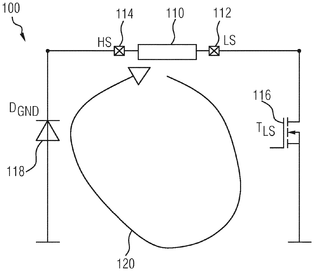
[0036] figure 1 A circuit diagram 100 shows a portion of a circuit for actuating a fuel injector 110 according to one embodiment. Fuel injector 110 has terminals 112 (low side LS) and 114 (high side HS). Terminal 112 is connected to transistor 116 (low side transistor T LS ), and can therefore be grounded. terminal 114 through diode 118 (freewheeling diode D GND ) to ground.

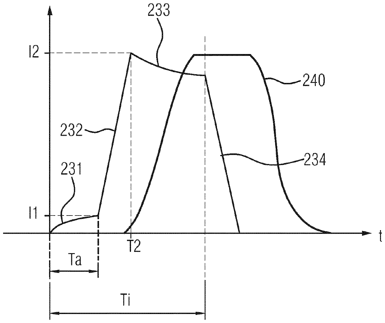
[0037] figure 2 Graph 201 shows exemplary time current curves 231 - 234 according to one embodiment. Diagram 201 also shows the temporal profile of fuel quantity introduction 240 .

[0038] The following will refer to figure 1 and 2The actuation of the fuel injector according to the present invention will be described. In operation, transistor 116 is actuated so that terminal 112 is grounded. If there is residual magnetization in fuel injec...


PUM


Abstract

The invention relates to a method for actuating a fuel injector, which has a magnetic coil drive, for an internal combustion engine of a motor vehicle. The fuel injector has a first connection and a second connection, wherein the first connection can be connected to ground via a switch element, and the second connection is connected to ground. The method has the following steps: (a) actuating theswitch element in order to connect the first connection to ground, (b) detecting a time curve of the current strength of a current flowing through the magnetic coil drive, and (c) applying a voltage pulse to the magnetic coil drive in order to initiate an opening process of the fuel injector. A duration of the voltage pulse is determined on the basis of the detected time curve of the current strength. The invention further relates to a motor control and to a computer program.

Description

technical field [0001] The invention relates to the technical field of actuation of fuel injectors, in particular to a method for actuating a fuel injector with a magnetic coil drive for an internal combustion engine of a motor vehicle. Furthermore, the invention relates to an engine controller and a computer program. Background technique [0002] In the case of the operation of fuel injectors with a magnetic coil drive, due to capacitance differences, different sequential opening behaviors of the individual injectors and thus corresponding variations in the injection quantities result. [0003] As the injection time and / or electro / hydraulic separation time becomes shorter, the relative injection quantity difference between each injector and between injections increases. These relative magnitude differences are so far small and of no real significance. The ever-increasing and increasing variation of the injection quantity and number of injections per injection cycle (sever...

Claims


Application Information

Patent Timeline
Patent Type & Authority Applications(China)
IPC IPC(8): F02D41/20F02D41/40
CPCF02D41/20F02D41/402F02D2041/2003F02D2041/2041F02D2041/2044F02D2041/2058Y02T10/40F02D2041/2051
Inventor F.邓克
Owner VTESCO TECH GMBH
Learn More