A New Type Disc Soil Divider

A ditching machine and disc-type technology, which is applied in the direction of excavation/covering trenches, planting methods, applications, etc., can solve the problems that affect the ditching efficiency of the ditching machine and the long throwing distance, and achieve novel structure and return Uniform force on the soil, easy to operate and use

Active Publication Date: 2017-03-08
SHANDONG GAOTANG XINHANG MACHINERY
View PDF6 Cites 0 Cited by
  • Summary
  • Abstract
  • Description
  • Claims
  • Application Information

AI Technical Summary

Problems solved by technology

There are two main problems in the soil dividing device of the trencher in the prior art: the one is that when the chain of the band tool of the trencher rotates, it is inevitable to bring back a part of the soil in the ditch that has been opened; The soil separated by the soil separation system is not thrown far enough, and accumulates on both sides of the trench. Over time, it collapses and returns to the trench
The above two factors seriously affect the ditching efficiency of the ditching machine

Method used


Image

  • A New Type Disc Soil Divider
  • A New Type Disc Soil Divider
  • A New Type Disc Soil Divider

Examples


Embodiment 2

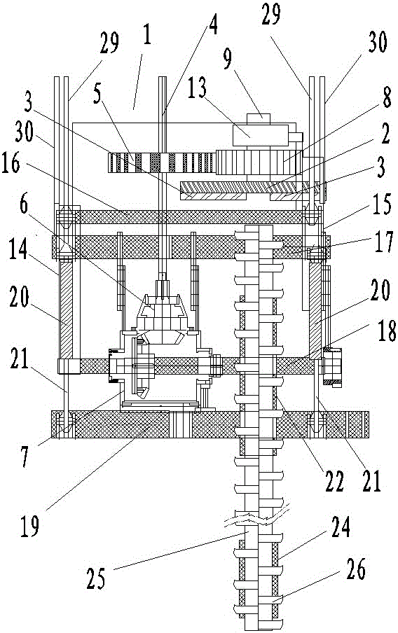
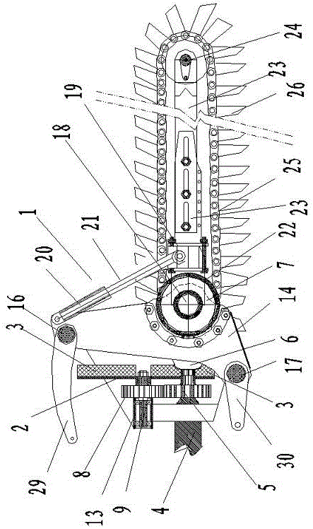
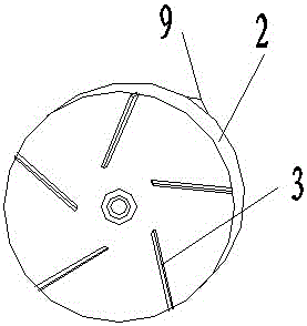
[0042] Example 2. Such as Figure 4 As shown, the only difference between this embodiment and Embodiment 1 is that the power transmission system includes the power take-off shaft 4 of the tractor, and the power take-off shaft 4 of the tractor is provided with a drive wheel; the front end of the power take-off shaft 4 is provided with a universal joint 6 , the universal joint 6 is connected with the gearbox 7 of the ditching tool system; the rotating shaft 9 of the soil dividing plate is installed on the frame body 1 through a bearing 13, and a transmission wheel 11 is arranged on the rotating shaft 9 of the dividing soil plate, and the dividing soil plate The transmission wheel 11 on the rotary shaft 9 of the tractor is connected with the transmission wheel 10 on the power output shaft 4 of the tractor by a belt 12 or a chain.

Embodiment 3

[0043] Example 3. Such as Figure 5 As shown, the only difference between this embodiment and Embodiment 1 is that the left and right ends of the support rod connecting plate 19 are provided with vertical plates 28, and the output shaft 21 of the hydraulic cylinder at the top of the left vertical plate 14 is connected with the support rod connecting plate 19. The vertical plate 28 at the left end is hinged, and the output shaft 21 of the hydraulic oil cylinder at the top of the right vertical plate 15 is hinged with the vertical plate at the right end of the support rod connecting plate 19 . The left and right ends of the support rod connecting plate 19 are provided with vertical plates 28, which increases the control range of the hydraulic cylinder to the supporting rod connecting plate 19 along the power output shaft 18 of the ditching tool.

Embodiment 4

[0044] Example 4. Such as Image 6 As shown, the only difference between this embodiment and Embodiment 1 is: the left and right ends of the ditching tool power output shaft 18 are hinged with connecting plates 27; The left end of 19 is hinged, and the connecting plate of the right-hand side of ditching cutter power output shaft 18 is hinged with the right-hand side of support bar connecting plate 19. With this structure, the rigidity of the device is improved.


PUM


Abstract

The invention discloses a novel disc-type soil-splitting ditching machine which comprises a rack body suspended at the rear end of a tractor. The rack body is provided with a ditching cutter system, a soil splitting disc and a power transmission system. The ditching cutter system is installed at the front end of the rack body. The soil splitting disc is installed behind the cutter system and on the rack body. The front side face of the soil splitting disc is perpendicular to the ground. Several vanes are arrayed annularly around the center of the front side face of the soil splitting disc. The ditching cutter system and the soil splitting disc are respectively connected to the power transmission system. When the soil splitting disc rotates around its axis, the soil splitting disc can throw soil transmitted onto the front side face of the soil splitting disc after ditching by the ditching cutter system. The novel disc-type soil-splitting ditching machine has a novel and reasonable structure, has a production and manufacturing technology, is low-cost, is convenient to install, adjust, operate and use, and is suitable for ditching work of dry hard and wet pieces of paddy field and various other kinds of pieces of paddy field. Backfill force is uniform, soil throwing is uniform. The novel disc-type soil-splitting ditching machine has good integrality, high strength, impact resistance and long service life, is smooth and is not easy to slime. Work efficiency is enhanced.

Description

technical field [0001] The invention relates to a construction machine tool for excavating trenches on land. Background technique [0002] The ditching machine is an efficient and practical ditching device. Generally, a soil dividing device is provided under the front or rear side of the ditching machine tool. The soil dividing device is generally a soil dividing plate, and the soil dividing plate is rotated by the ditching tool. The power of the ditch divides the soil generated by the ditch to both sides of the ditch. There is also a soil dividing device that uses a spiral soil divider to divide the soil. The spiral blades are used to divide the soil to both sides of the opened trench. There are two main problems in the soil dividing device of the trencher in the prior art: the one is that when the chain of the band tool of the trencher rotates, it is inevitable to bring back a part of the soil in the ditch that has been opened; The soil separated by the soil separation s...

Claims


Application Information

Patent Timeline
Patent Type & Authority Patents(China)
IPC IPC(8): A01C5/06
Inventor 陈万才
Owner SHANDONG GAOTANG XINHANG MACHINERY
Why Eureka
Try Eureka