
Bending machine

A bending machine and frame technology, applied in the field of bending machines, can solve problems such as inconvenient adjustment of bending angles, and achieve the effects of saving man-hours and being convenient to use

Inactive Publication Date: 2015-12-23
南通东海机床制造集团有限公司
View PDF0 Cites 8 Cited by
  • Summary
  • Abstract
  • Description
  • Claims
  • Application Information

AI Technical Summary

Problems solved by technology

[0003] In order to solve the problem of inconvenient adjustment of the bending angle of the existing electric bending machine, the present invention provides a bending machine, the bending angle can be adjusted at will according to the needs of the workpiece, which reduces the labor intensity of workers and saves working hours

Method used


Image

  • Bending machine

Examples


Embodiment Construction

[0010] The present invention will be further described below in conjunction with accompanying drawing.

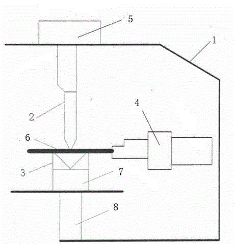
[0011] The structure of the present invention is as figure 1 As shown, including a frame 1, a power mechanism 5 is installed on the top of the frame 1, and the power mechanism 5 is connected with the upper mold 2 in the frame 1, and the corresponding position below the upper mold 2 is provided with a lower mold 3, and the lower mold 3 is installed on the machine. At the bottom of the frame 1, a feeding device 4 is provided in the horizontal direction between the upper mold 2 and the lower mold 3. The lower mold 3 is a triangle with two opposite hypotenuses, and a drive motor 7 is installed below the lower mold 3 to drive The motor 7 drives the triangular movement of the lower mold 3 to adjust the angle between the triangles, and the lower part of the driving motor 7 is connected with the frame 1 through the telescopic rod 8 .

[0012] During work, first according to workpi...


PUM


Abstract

The invention provides a bending machine which comprises a rack, wherein a power mechanism is installed on the upper part of the rack, the power mechanism is connected to an upper die inside the rack, a lower die is disposed at a corresponding position under the upper die, the lower dies is installed on the bottom of the rack, a feeding device is disposed horizontally between the upper die and the lower die, the lower die comprises two triangles with two opposite inclined edges, a driving motor is installed under the lower die, the driving motor drives the triangles of the lower die to move, an included angle between the triangles is adjusted, and the lower part of the driving motor is connected to the rack by an stretchable rod. The bending machine provided by the invention makes the driving motor adjust the included angle of the lower die in order to adjust a bending angle, is used conveniently and saves working hours. By controlling height of the lower die using the stretchable rod, working demands of different work pieces can be adapted.

Description

technical field [0001] The invention relates to the field of hardware tools, in particular to a bending machine. Background technique [0002] The bending machine is divided into manual bending machine, hydraulic bending machine and CNC bending machine. Manual bending machine is divided into mechanical manual bending machine and electric manual bending machine, and hydraulic bending machine can be divided into synchronous mode: torsion shaft synchronous, machine-hydraulic synchronous, and electro-hydraulic synchronous. According to the movement mode, the hydraulic bending machine can be divided into: up-moving type and down-moving type. The operation of the electric bending machine in the prior art is complicated, and the bending angle is relatively single. Adjusting the bending angle is usually realized by replacing the lower mold, which is time-consuming and laborious. Contents of the invention [0003] In order to solve the problem of inconvenient adjustment of the be...

Claims


Application Information

Patent Timeline
Patent Type & Authority Applications(China)
IPC IPC(8): B21D5/06
Inventor 陈宝银
Owner 南通东海机床制造集团有限公司
Learn More