Magnetic collector for magnetic pulse forming

A magnetic pulse forming and magnetic collector technology, applied in the field of magnetic collectors, can solve the problems of forming production chain damage, short-circuit of the longitudinal seam of the magnetic collector and structural damage, reduction of the insulation capacity of the magnetic collector, etc. Effect

Inactive Publication Date: 2015-12-23
HARBIN INST OF TECH
View PDF7 Cites 11 Cited by
  • Summary
  • Abstract
  • Description
  • Claims
  • Application Information

AI Technical Summary

Benefits of technology

This patented technology improves on existing methods such as magnets or coils while still maintain their effectiveness at higher frequencies (upwards). It uses an external channel filled with special materials called crystals made from cerium oxide) which helps reduce friction when they are moved through them under strong pressure. By doing this, it prevents damage caused by thermal expansion and allows longer use without losing its function over time. Additionally, there're also included features like spiral grooves inside the pipings themselves to further enhance the efficiency of the device. Overall, these technical improvements improve the durability and reliability of current devices.

Problems solved by technology

This patented describes a type of magneque pulser (MPS), commonly called MPS). It involves creating tiny structures made up of thin sheets of material onto another piece of material undergoing fabricating operations like injection molds. These structures help shape complex metallic shapes without being damaged during these steps. However, current methods require long hours before each step results in poor product quality due to thermal stress issues associated with the use of strong permanent magnetism. To address this issue, some proposed solutions involve utilizing specialized tools and techniques to quickly respond to changes in the environment while maintaining good performance and controllability over large scale industrial applications.

Method used


Image

  • Magnetic collector for magnetic pulse forming
  • Magnetic collector for magnetic pulse forming
  • Magnetic collector for magnetic pulse forming

Examples


specific Embodiment approach 1

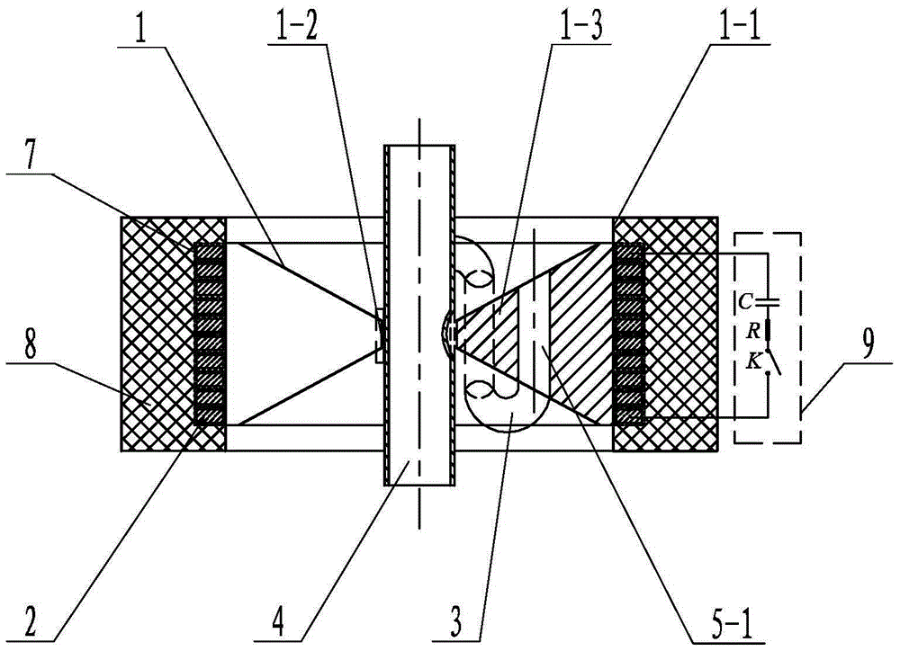
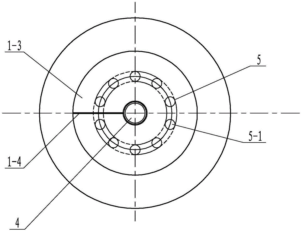
[0020] Specific implementation mode one: combine figure 1 and figure 2 Describe this embodiment. This embodiment includes a magnetic collector body 1 and a coil 2. The magnetic collector body 1 includes an outer casing 1-1, an inner casing 1-2, and a longitudinal arm 1-3. The coil 2 is sleeved on the outer casing. Outside the body 1-1, the outer wall of the outer body 1-1 is set opposite to the inner wall of the coil 2, the inner body 1-2 is set inside the outer body 1-1, and the inner body 1-2 is provided with a tube blank 4, and the inner body 1-2 The inner wall of the sleeve body 1-2 is set opposite to the outer wall of the tube blank 4, and the outer sleeve body 1-1 and the inner sleeve body 1-2 are fixed and connected as a whole through the longitudinal arm 1-3. There is a longitudinal slit 1-4 in the process, the outer casing 1-1, the inner casing 1-2 and the longitudinal arm 1-3 are cut apart by the longitudinal slit 1-4, and insulating material is added in the longit...

specific Embodiment approach 2

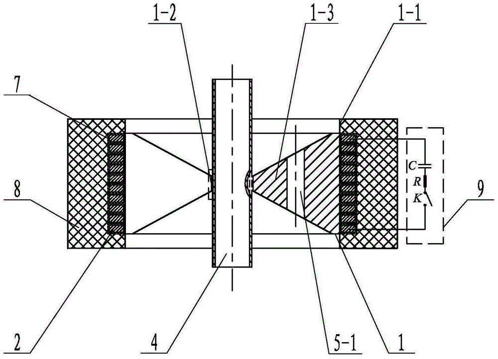
[0023] Specific implementation mode two: combination figure 1 and figure 2 To describe this embodiment, the longitudinal section of the magnet collector body 1 in this embodiment is trapezoidal or T-shaped. The magnetic collector can be a single-slit overall structure or a symmetrical split structure. The cross-sectional shape of the magnetic collector can be trapezoidal or approximately trapezoidal, or T-shaped. Other structures and connections are the same as those in the first embodiment.

specific Embodiment approach 3

[0024] Specific implementation mode three: combination figure 1 and figure 2 The present embodiment is described. In this embodiment, the longitudinal length of the inner sleeve body 1-2 is smaller than the longitudinal length of the outer sleeve body 1-1. Other structures and connections are the same as those in the first or second embodiment.


PUM


Abstract

The invention discloses a magnetic collector for magnetic pulse forming, and relates to a magnetic collector. The invention aims at solving the problem that the structural strength of a magnetic collector, the insulation capacity of the gap of a longitudinal joint of the magnetic collector, and the insulation capacity between a working area of the magnetic collector and the machined workpiece are reduced due to a rapid temperature rise generated during a continuous magnetic pulse forming process, so that short circuit and structural damages among the longitudinal joint of the magnetic collector, the magnetic collector and the workpiece are caused, and finally the formation production chain is broken. According to the invention, at least one cooling channel ring is machined on a longitudinal arm; each cooling channel ring comprises a plurality of cooling channels; each cooling channel penetrates through an inner sleeve body in the longitudinal length direction and is internally charged with a refrigeration gas or a refrigeration liquid; and every two cooling channels are communicated through an external tube so as to form a serial cooling pipeline or a parallel cooling pipeline; and the Joule heat generated by the magnetic collector during multiple charge-discharge processes is brought away by charging the refrigeration gas or the refrigeration liquid in the cooling channel rings, thus effectively assisting to cool the magnetic collector. The magnetic collector disclosed by the invention is used in a magnetic pulse forming process.

Description


Claims


Application Information

Patent Timeline
Owner HARBIN INST OF TECH
Why Eureka
Try Eureka