
Automatic distance measurement shear production line

A production line and ranging technology, applied in other manufacturing equipment/tools, manufacturing tools, etc., can solve problems such as high labor costs, low efficiency, and inaccurate calculations, and achieve the effects of saving manufacturing costs, high efficiency, and good stability

Active Publication Date: 2015-12-23
MAANSHAN JINGSHUN METAL PROCESSING
View PDF7 Cites 0 Cited by
  • Summary
  • Abstract
  • Description
  • Claims
  • Application Information

AI Technical Summary

Problems solved by technology

[0005] Aiming at the problems of inaccurate calculation of the steel plate distance, high labor cost and low efficiency existing in the prior art when the plate shearing machine is shearing the plate, the present invention provides an automatic distance measuring and shearing production line, which can realize multi-directional detection of the steel plate size Calculate and control the vertical entry of the steel plate into the cutting edge, with high efficiency and low labor cost

Method used


Image

  • Automatic distance measurement shear production line
  • Automatic distance measurement shear production line

Examples


Embodiment 1

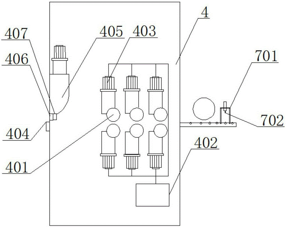
[0029] Such as figure 1 As shown, the automatic distance measuring and shearing production line includes an unwinding machine 1, a primary leveling machine 2, a distance measuring roller 3, a conveyor belt 5, a receiving machine 6 and a transition conveyor belt 8, and also includes a secondary leveling and shearing machine 4 and The probe module 7, the unwinding machine 1, the primary leveling machine 2, the transition conveyor belt 8, the secondary leveling machine 4, the conveyor belt 5 and the receiving machine 6 are connected in sequence, and the probe module 7 and the distance measuring roller 3 sequentially arranged above the transition conveyor belt 8;

[0030] Such as figure 2 As shown, the secondary leveling and shearing machine 4 includes a leveling roller 401, a control box 402, a drive motor 403, a lower knife 404, a slider 405, an upper knife 406 and a vertical distance measuring device 407, the described The bottom of the slide block 405 facing the entrance of...

Embodiment 2

[0035] Such as figure 1 As shown, the automatic distance measuring and shearing production line includes an unwinding machine 1, a primary leveling machine 2, a distance measuring roller 3, a conveyor belt 5, a receiving machine 6 and a transition conveyor belt 8, and also includes a secondary leveling and shearing machine 4 and The probe module 7, the unwinding machine 1, the primary leveling machine 2, the transition conveyor belt 8, the secondary leveling machine 4, the conveyor belt 5 and the receiving machine 6 are connected in sequence, and the probe module 7 and the distance measuring roller 3 sequentially arranged above the transition conveyor belt 8;

[0036] Such as figure 2 As shown, the secondary leveling and shearing machine 4 includes a leveling roller 401, a control box 402, a drive motor 403, a lower knife 404, a slider 405, an upper knife 406 and a vertical distance measuring device 407, the described The bottom of the slide block 405 facing the entrance of...


PUM


Abstract

The invention discloses an automatic distance measurement shear production line, and belongs to the technical field of processing of shear plates. The automatic distance measurement shear production line comprises an unwinding device (1), a primary leveling machine (2), a distance measurement roller (3), a conveying belt (5), a material receiving machine (6) and a transition conveying belt (5), and is characterized by comprising a secondary leveling shear machine (4) and a probe module, wherein the unwinding device (1), the primary leveling machine (2), the transition conveying belt (5), the secondary leveling shear machine (4), the conveying belt (5) and the material receiving machine (6) are sequentially connected, and the probe module (7) and the distance measurement roller (3) are sequentially arranged above the transition conveying belt (5). The multi-direction detection and calculation for the size of steel sheets and controlling the steel sheet to vertically enter into a knife edge of the shear plate can be achieved, the efficiency is high, and the manual cost is low.

Description

technical field [0001] The invention relates to the field of plate shearing processing, and more specifically relates to an automatic distance-measuring and shearing production line. Background technique [0002] The cut-to-length shear in the prior art includes a conveying roller table, a pinch roller device and a plate shearing machine for accurately feeding the plate; during work, the distance length of the conveyed steel plate is measured by the pinch roller device, and according to the pinch roller The number of turns of the roller device is used to measure the running length of the steel plate, locate the distance of the steel plate, and cut the steel plate after starting the conveying roller table. However, this shearing method has large dimensional errors and manual observation. The consistency is poor, the efficiency is low, and the operator Tired easily. [0003] In the prior art, there is an improvement on the distance measuring method of the pinch roller. Chines...

Claims


Application Information

Patent Timeline
Patent Type & Authority Applications(China)
IPC IPC(8): B23P23/06B21C37/02
CPCB21C37/02B23P23/06
Inventor 周建峰
Owner MAANSHAN JINGSHUN METAL PROCESSING
Learn More