
High-pressure extrusion molding machine

An extrusion molding machine, high pressure technology, applied in the field of continuous production of thin-wall honeycomb SCR catalyst extrusion molding, can solve the problems of inconsistent product hardness, increase production costs, water leakage, etc., to ensure smooth continuous production, increase extrusion The effect of reducing pressure and reducing manufacturing costs

Active Publication Date: 2015-12-23
ZHEJIANG GUANGHAN ENVIRONMENTAL PROTECTION TECH
View PDF4 Cites 4 Cited by
  • Summary
  • Abstract
  • Description
  • Claims
  • Application Information

AI Technical Summary

Problems solved by technology

In the production of catalysts with a wall thickness of less than 1.0, problems such as deterioration of material properties, hard materials and blockage of molds often occur during equipment operation, which brings great inconvenience to the production process, resulting in reduced output, high energy consumption, and large waste of manpower and material resources. , which increases the cost of the product
[0003] In the existing extrusion molding machine, the main and auxiliary screws are assembled in a multi-section connection mode. The spiral joints at the joints are inconsistent, the misalignment deviation is large, and the sealing device design at the joints is insufficient, which often causes water leakage and wastes materials during production. Big
Existing extrusion molding equipment, the design of the cooling system is unreasonable, the cooling temperature of the screw and the cooling temperature of the barrel are very different, resulting in a temperature difference between the surface of the product and the center of the product during the production process, affecting the yield, and even causing the product to be damaged. Inconsistent external hardness affects the drying process, easily produces waste products, wastes raw materials, and increases manufacturing costs

Method used


Image

  • High-pressure extrusion molding machine
  • High-pressure extrusion molding machine
  • High-pressure extrusion molding machine

Examples


Embodiment Construction

[0025] Refer to attached picture.

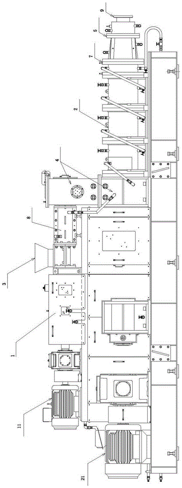
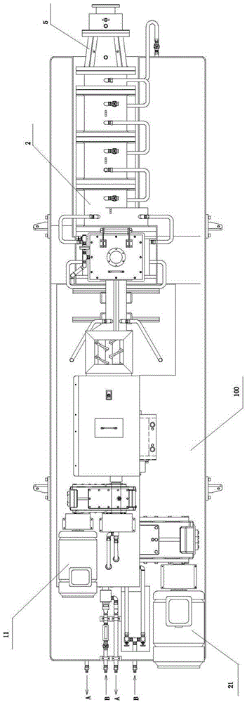
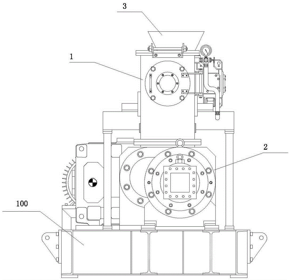
[0026] The high-pressure extrusion molding machine includes a frame 100. The frame 100 is provided with an upper-level feeding mechanism 1 and a lower-level feeding mechanism 2. The upper-level feeding mechanism 1 is connected to the hopper 3. The upper-level feeding mechanism 1 is arranged above the lower-level feeding mechanism 2. The upper-level feeding mechanism 1 and the lower feeding mechanism 2 both carry out horizontal material transportation through the screw, and the upper feeding mechanism 1 and the lower feeding mechanism 2 are connected through the vacuum chamber 4, and the conveyed materials pass through the vacuum chamber 4 after being squeezed and conveyed by the upper feeding mechanism 1 , through the vacuum chamber 4 into the lower feeding mechanism 2 for secondary extrusion conveying, the outlet of the lower feeding mechanism 2 is connected with an extension pipe 5, which is used to extrude the conveyed material; the high p...


PUM


Abstract

The invention provides a high-pressure extrusion molding machine which comprises an upper-grade feeding mechanism and a lower-grade feeding mechanism. The upper-grade feeding mechanism is connected with a hopper, and the upper-grade feeding mechanism and the lower-grade feeding mechanism both transversely convey materials through screw rods and are connected through a vacuum chamber; the conveyed materials are extruded and conveyed by the upper-grade feeding mechanism, then pass through the vacuum chamber and enter the lower-grade feeding mechanism to be secondarily extruded and conveyed; an outlet of the lower-grade feeding mechanism is connected with an extending pipe. The high-pressure extrusion molding machine further comprises a cooling loop system. According to the high-pressure extrusion molding machine, the structures and extrusion sections of the screw rods are improved, 15MPa high-pressure extrusion molding is achieved, and the requirements of a continuous extrusion production process for thin-walled selective catalytic reduction (SCR) honeycomb type catalysts can be met; the technical problem of continuous extrusion production of horizontal large-hole-diameter thin-walled honeycomb type SCR catalysts is solved, the production efficiency is improved, and the manufacturing cost of products is lowered.

Description

technical field [0001] The invention relates to the technical field of horizontal high-pressure extrusion molding, in particular to a continuous production technology suitable for thin-wall honeycomb SCR catalyst extrusion molding. Background technique [0002] The SCR honeycomb extrusion molding machine is a thick-walled equipment. The maximum extrusion pressure during the production process is 9MPa, and the maximum extrusion speed is 2.5m / min. It is suitable for catalyst production lines with a wall thickness of 1.0 or more. In the production of catalysts with a wall thickness of less than 1.0, problems such as deterioration of material properties, hard materials and blockage of molds often occur during equipment operation, which brings great inconvenience to the production process, resulting in reduced output, high energy consumption, and large waste of manpower and material resources. , increasing the cost of the product. [0003] In the existing extrusion molding machi...

Claims


Application Information

Patent Timeline
Patent Type & Authority Applications(China)
IPC IPC(8): B29C47/10B29C47/78B29C47/38B29C48/395
CPCB29C48/298B29C48/397B29C48/797
Inventor 叶力平郑光静焦娟霞
Owner ZHEJIANG GUANGHAN ENVIRONMENTAL PROTECTION TECH
Learn More