
A lifting fixture for tubular components

A technology for parts and fixtures, applied in the field of hoisting fixtures for tubular parts, can solve the problems of high use cost, damage to workpieces, and heavy structural weight, and achieve the effects of reducing the risk of falling, saving production costs, and having a simple solution structure.

Active Publication Date: 2017-08-25
ANHUI JIANGHUAI AUTOMOBILE GRP CORP LTD
View PDF7 Cites 0 Cited by
  • Summary
  • Abstract
  • Description
  • Claims
  • Application Information

AI Technical Summary

Problems solved by technology

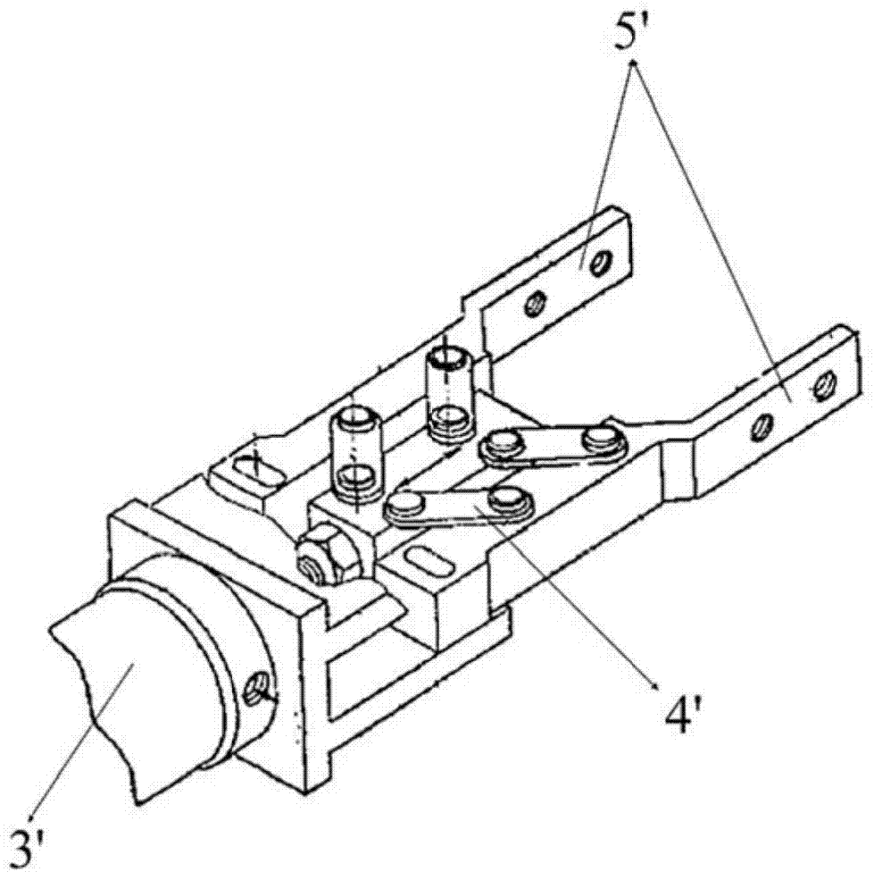
The clamping spreader ensures the stability and accurate positioning of the workpiece during the grabbing process, but the structure is relatively complicated, the use cost is high, and the need for an external air source is not conducive to long-distance lifting
In addition, the weight of the structure in this solution is heavy and the clamping switch needs to be controlled, which is not easy to operate; the clamping force generated by the clamping claws is also difficult to determine. If it is too large, it will damage the workpiece, but if it is too small, it will easily slip.

Method used


Image

  • A lifting fixture for tubular components
  • A lifting fixture for tubular components
  • A lifting fixture for tubular components

Examples


Embodiment Construction

[0028] In order to enable those skilled in the art to better understand the technical solution of the present invention, the solution will be further described in detail below in conjunction with specific embodiments.

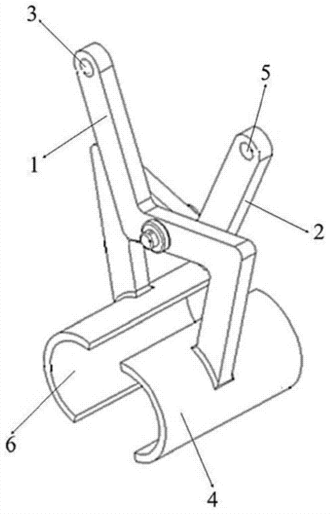
[0029] refer to image 3 and Figure 4 , the lifting fixture for tubular parts provided by the embodiment of the present invention includes a first clamping arm 1 and a second clamping arm 2 hinged together; one end of the first clamping arm 1 is provided with a first lifting arm Picking point 3, a first clamping portion 4 is provided at the opposite end, a second lifting point 5 is provided at one end of the second clamping arm 2 close to the first lifting point 3, and a second lifting point 5 is provided at the opposite end A second clamping portion 6 is provided; the first clamping portion 4 and the second clamping portion 6 form an accommodating space 7 for tubular components.

[0030] When the pipe fitting is placed in the accommodating space 7 and hoist...


PUM


Abstract

The invention relates to the technical field of hoisting, and discloses a hoisting fixture for tubular components, comprising a first clamping arm and a second clamping arm hinged together; one end of the first clamping arm is provided with a first A lifting point, the opposite end is provided with a first clamping part, one end of the second clamping arm close to the first lifting point is provided with a second lifting point, and the opposite end is provided with a second Clamping portion; the first clamping portion and the second clamping portion form an accommodating space for tubular components. The hoisting fixture utilizes the weight of the tubular part itself to generate clamping force, realizes the convenient and stable grasping and lifting of the tubular workpiece, and has a simple structure, convenient operation and low cost.

Description

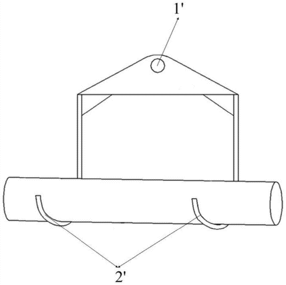
technical field [0001] The invention relates to the technical field of hoisting, in particular to a hoisting fixture for tubular components. Background technique [0002] Since the surface of tubular parts (such as exhaust pipes, transmission shafts, etc.) is arc-shaped, the contact surface with the spreader is small during the grabbing process, and it is easy to slide and rotate. Therefore, multi-point hanging or relying on external force is often used The clamping method is used for lifting and conveying. [0003] refer to figure 1 , is a schematic diagram of a multi-point hanging spreader used in the prior art. The top end of the spreader has a lifting hole 1', and the bottom end has two sets of hooks 2' arranged in parallel, and the pipe is placed in the hooks 2' for lifting. Although the sling can grab and lift the pipe, the workpiece may still be displaced and rotated in the radial or axial direction. The uncertain movement of the workpiece during the lifting and i...

Claims


Application Information

Patent Timeline
Patent Type & Authority Patents(China)
IPC IPC(8): B66C1/42
Inventor 何志远陈雪
Owner ANHUI JIANGHUAI AUTOMOBILE GRP CORP LTD
Learn More