A gas drilling surface manifold connection structure

A technology of gas drilling and connection structure, which is applied in the direction of earthwork drilling, wellbore flushing, wellbore/well parts, etc., and can solve the problems of cumbersome maintenance and drill bit replacement, the effect of reverse circulation formation, and the inability to establish annular pressure, etc. , to prevent the disturbed collapse of the borehole wall, improve the drilling efficiency and save the gas volume

Active Publication Date: 2018-03-30
BC P INC CHINA NAT PETROLEUM CORP +1
View PDF8 Cites 0 Cited by
  • Summary
  • Abstract
  • Description
  • Claims
  • Application Information

AI Technical Summary

Problems solved by technology

This method is mainly used for reaming drilling in the coal mine industry, and has high requirements on the formation. If the formation fractures develop, the annular pressure cannot be established, and the effect of reverse circulation formation will also be affected.
At the same time, the rock-breaking tool used in this construction method is a cluster DTH hammer. The structure of this tool is a bit complicated, and maintenance and replacement of drill bits are a bit cumbersome.

Method used


Image

  • A gas drilling surface manifold connection structure
  • A gas drilling surface manifold connection structure

Examples


Embodiment 1

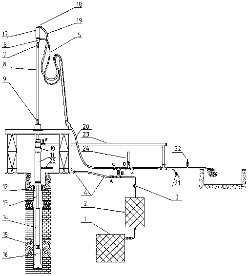
[0031]As a preferred embodiment of the present invention, it includes: gas injection unit 1, pressure relief unit 2, flow meter 3, ground gas injection manifold 4, high-pressure gas injection hose 5, erosion-resistant gooseneck 18, high-pressure reactor Circulating sand discharge hose 19, surface reverse circulation sand discharge pipeline 20 and positive circulation gas drilling sand discharge pipeline 23,

[0032] Wherein: the gas injection unit 1 is connected to the pressure relief unit 2 through a high-pressure pipeline, the flow meter 3 is installed at the outlet of the pressure relief unit 2, the upstream of the flow meter 3 is connected to the pressure relief unit 2, the downstream is connected to the ground gas injection manifold 4, and the ground injection The trachea manifold 4 is connected to the high-pressure gas injection hose 5;

[0033] The outlet of the erosion-resistant gooseneck 18 is connected to the high-pressure reverse circulation sand discharge hose 19, ...

Embodiment 2

[0037] On the basis of the above-mentioned embodiments, a sampling sub-joint 21 and a dedusting water sub-joint 22 are installed on the reverse circulation sand discharge pipeline 20 leading to the grit chamber. The gas injection unit 1 provides high-pressure gas, including an air compressor and a supercharger. The left end of the cross is connected to the ground reverse circulation sand discharge pipeline 20 through the valve C, the right end is connected to a tee through the valve E, the upper end is connected to the mud pump 24 through the valve D, and the lower end is connected to the ground gas injection manifold 4 through the valve B, and the ground gas injection manifold 4 A valve A is also arranged between connecting with the high-pressure gas injection hose 5 .

Embodiment 3

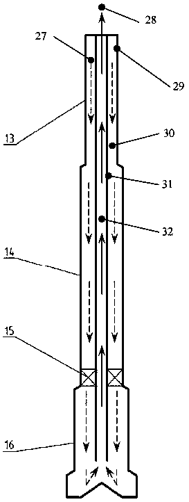
[0039] A specific application example of the present invention: a full-section self-priming reverse circulation gas drilling system is composed of the following equipment and tools: gas injection unit 1, pressure relief unit 2, flow meter 3, surface gas injection manifold 4, high-pressure gas injection Hose 5, gas distribution joint 6, double-wall upper cock 7, double-wall kelly 8, double-wall lower cock 9, double-wall drill pipe 10, double-wall drill collar 11, annular check valve 12, reverse circulation rock breaking Tools (reverse circulation air hammer, reverse circulation roller cone bit or reverse circulation PDC bit) 13, double-walled drill pipe 14, wellhead device 15, rotary blowout preventer 16, faucet (or top drive) 17, erosion-resistant gooseneck 18. High-pressure reverse circulation sand discharge hose 19, ground reverse circulation sand discharge pipeline 20, sampling nipple 21, dust-falling water nipple 22, positive circulation gas drilling sand discharge pipeline...


PUM


Abstract

The invention discloses a gas drilling ground manifold connection structure, comprising: a gas injection unit, a pressure relief unit, a flow meter, a ground gas injection manifold, a high-pressure gas injection hose, an erosion-resistant gooseneck, and a high-pressure reverse circulation sand discharge Hose, surface reverse circulation sand discharge pipeline and positive circulation gas drilling sand discharge pipeline, apply this surface manifold connection structure to the self-priming reverse circulation gas drilling system of the whole well section, without the need for conventional single-wall drilling tools and gas-water mixing With the participation of joints and other tools, air is used as the circulation medium in the whole well section, and reverse circulation can be formed without the participation of mud or other drilling fluids, especially suitable for well sections with severe water shortage, serious lost circulation or where gas lift reverse circulation cannot be implemented .

Description

technical field [0001] The invention relates to the technical field of petroleum and natural gas drilling, in particular to a gas drilling ground manifold connection structure. Background technique [0002] Gas drilling technology can greatly increase the ROP in difficult-to-drill formations such as volcanic rocks, gravel layers, clastic rocks, and carbonate rocks. It is applied in areas such as Sichuan and Chongqing, and the average ROP is increased by 4 to 15 times. However, when positive circulation gas is used to drill wells (especially large-diameter wells), equipment investment is large, land occupation is large, gas consumption is large, energy consumption is high, and cost is high. 3 / min or more, 17 1 / 2″ borehole required gas volume 300m 3 / min; when the stability of the borehole wall is poor, or the formation water yield is large, increasing the gas volume for gas drilling will intensify the erosion of the borehole wall and increase the possibility of borehole wal...

Claims


Application Information

Patent Timeline
Patent Type & Authority Patents(China)
IPC IPC(8): E21B21/00
Inventor 范黎明韩烈祥刘殿琛董仕明廖兵罗群
Owner BC P INC CHINA NAT PETROLEUM CORP
Why Eureka
Try Eureka