Reverse circulation gas drilling tool combination structure

A gas drilling and drilling tool assembly technology, applied in construction and other fields, can solve problems such as cumbersome maintenance and replacement of drill bits, influence of reverse circulation formation effect, and inability to establish annular pressure, so as to prevent the disturbed collapse of the borehole wall and improve drilling efficiency. Efficiency and gas saving effect

Inactive Publication Date: 2015-12-09
CHINA NAT PETROLEUM CORP CHUANQING DRILLING ENG CO LTD
View PDF10 Cites 5 Cited by
  • Summary
  • Abstract
  • Description
  • Claims
  • Application Information

AI Technical Summary

Problems solved by technology

This method is mainly used for reaming drilling in the coal mine industry, and has high requirements on the formation. If the formation fractures develop, the annular pressure cannot be established, and the effect of reverse circulation formation will also be affected.
At the same time, the rock-breaking tool used in this construction method is a cluster DTH hammer. The structure of this tool is a bit complicated, and maintenance and replacement of drill bits are a bit cumbersome.

Method used


Image

  • Reverse circulation gas drilling tool combination structure
  • Reverse circulation gas drilling tool combination structure

Examples


Embodiment 1

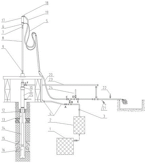
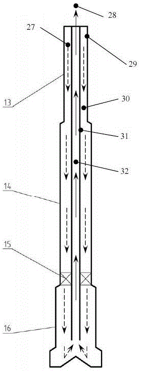
[0031] As another preferred embodiment of the present invention, it includes a faucet or a top drive 17, a gas distribution joint 6, a double-wall upper cock 7, a double-wall kelly 8, a double-wall lower cock 9, a rotary blowout preventer 10, a sleeve Pipe 12, double-wall drill pipe 13, double-wall drill collar 14, annular check valve 15 and gas reverse circulation rock breaking tool 16, wherein:

[0032] The erosion-resistant gooseneck 18 is connected to the faucet or the top drive 17, the high-pressure gas injection hose 5 is connected to the gas distribution joint 6, and the positive circulation gas drilling sand discharge pipeline 23 is connected to the casing side outlet of the rotary blowout preventer 10;

[0033]The lower end of the faucet is connected to the gas distribution joint 6 through threads, the lower end of the gas distribution joint 6 is connected to the double-wall upper cock 7 through threads, the double-wall upper cock 7 is connected to the double-wall kell...

Embodiment 2

[0038] On the basis of the above embodiments, a throttle manifold 25 is provided on one side of the wellhead 11 . The positive circulation gas drilling sand discharge pipeline 23 is connected to the casing side outlet of the rotary blowout preventer 10 through a valve F. Said high pressure refers to a pressure not lower than 21MPa.

Embodiment 3

[0040] A specific application example of the present invention: a full-section self-priming reverse circulation gas drilling system is composed of the following equipment and tools: gas injection unit 1, pressure relief unit 2, flow meter 3, surface gas injection manifold 4, high-pressure gas injection Hose 5, gas distribution joint 6, double-wall upper cock 7, double-wall kelly 8, double-wall lower cock 9, double-wall drill pipe 10, double-wall drill collar 11, annular check valve 12, reverse circulation rock breaking Tools (reverse circulation air hammer, reverse circulation roller cone bit or reverse circulation PDC bit) 13, double-walled drill pipe 14, wellhead device 15, rotary blowout preventer 16, faucet (or top drive) 17, erosion-resistant gooseneck 18. High-pressure reverse circulation sand discharge hose 19, ground reverse circulation sand discharge pipeline 20, sampling nipple 21, dust-falling water nipple 22, positive circulation gas drilling sand discharge pipeline...


PUM


Abstract

The invention discloses a reverse circulation gas drilling tool combination structure which comprises a tap or a top drive, a gas distribution joint, a double-wall upper cock, a double-wall kelly bar, a double-wall lower cock, a rotary blowout preventer, a sleeve, a double-wall drill pipe, a double-wall drill collar, an annular check valve and a gas reverse circulation rock breaking tool. When the drilling tool combination structure is applied to a full-hole self-suction reverse circulation gas drilling system, participation of tools, such as conventional single-wall drilling tools and gas and water mixed joints, is not needed, a full hole takes air as a circulating medium, reverse circulation can be formed without participation of slurry or other drilling fluids, and thus the drilling tool combination structure is particularly suitable for well sections which severely lack water, severely leak or can not implement air-lift reverse circulation.

Description

technical field [0001] The invention relates to the technical field of oil and gas drilling, in particular to a reverse circulation gas drilling tool assembly structure. Background technique [0002] Gas drilling technology can greatly increase the ROP in difficult-to-drill formations such as volcanic rocks, gravel layers, clastic rocks, and carbonate rocks. It is applied in areas such as Sichuan and Chongqing, and the average ROP is increased by 4 to 15 times. However, when positive circulation gas is used to drill wells (especially large-diameter wells), equipment investment is large, land occupation is large, gas consumption is large, energy consumption is high, and cost is high. 3 / min or more, 171 / 2″ borehole required gas volume of 300m 3 / min; when the stability of the borehole wall is poor, or the formation water yield is large, increasing the gas volume for gas drilling will intensify the erosion of the borehole wall and increase the possibility of borehole wall ins...

Claims


Application Information

Patent Timeline
Patent Type & Authority Applications(China)
IPC IPC(8): E21B21/16
Inventor 范黎明曾绍清周长虹王虎李宬晓吴俊
Owner CHINA NAT PETROLEUM CORP CHUANQING DRILLING ENG CO LTD
Why Eureka
Try Eureka