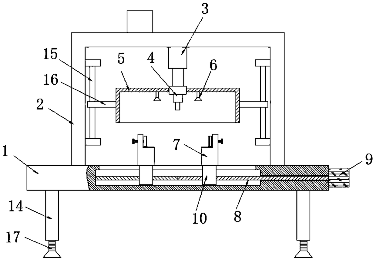
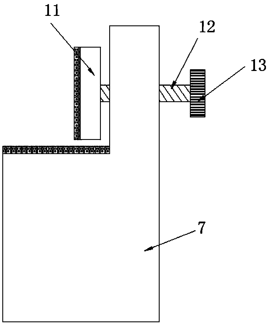
Numerical control equipment for plate drilling

A technology of numerical control equipment and plates, applied in drilling/drilling equipment, boring/drilling, metal processing equipment, etc. The effect of efficiency

Inactive Publication Date: 2018-11-16
佛山元聚数控设备有限公司
View PDF0 Cites 31 Cited by
  • Summary
  • Abstract
  • Description
  • Claims
  • Application Information

AI Technical Summary

Problems solved by technology

[0004] The purpose of the present invention is to solve the problem that the numerical control equipment for plate drilling in the prior art needs to rely on the staff to complete the drilling operation manually, so that there is a disadvantage of low drilling efficiency, and it is easy to hurt the staff during the drilling process. There is a big safety hazard problem, and a kind of numerical control equipment for plate drilling is proposed

Method used


Image

  • Numerical control equipment for plate drilling
  • Numerical control equipment for plate drilling

Examples


Embodiment Construction

[0021] The following will clearly and completely describe the technical solutions in the embodiments of the present invention with reference to the accompanying drawings in the embodiments of the present invention. Obviously, the described embodiments are only some, not all, embodiments of the present invention.

[0022] In describing the present invention, it should be understood that the terms "upper", "lower", "front", "rear", "left", "right", "top", "bottom", "inner", " The orientation or positional relationship indicated by "outside", etc. is based on the orientation or positional relationship shown in the drawings, and is only for the convenience of describing the present invention and simplifying the description, rather than indicating or implying that the referred device or element must have a specific orientation, so as to Specific orientation configurations and operations, therefore, are not to be construed as limitations on the invention.

[0023] refer to Figure ...


PUM


Abstract

The invention discloses numerical control equipment for plate drilling. The numerical control equipment comprises a worktable and a gantry arranged on the worktable, the lower end of a beam of the gantry is fixedly provided with a hydraulic rod, the lower end of a piston rod of the hydraulic rod is fixedly provided with a drilling machine, the side wall of the drilling machine is fixedly providedwith a protective cover, the inner wall of the upper end of the protective cover is fixedly provided with two dust collecting covers, and the two dust collecting covers are in central symmetry about the drilling machine; the upper end of the worktable is symmetrically and fixedly provided with two L-shaped fixing bases, and a clamping mechanism is arranged at a vertical part of each L-shaped fixing base; the worktable is internally provided with a cavity, a first screw is transversely arranged in the cavity, and one end of the first screw is rotatably connected with the left side wall of the cavity. The numerical control equipment is convenient to operate, the damage to the human body in the drilling process can be avoided, and the plate drilling efficiency is improved.

Description

technical field [0001] The invention relates to the technical field of numerical control equipment, in particular to a numerical control equipment used for plate drilling. Background technique [0002] With the continuous development of the machinery industry, various mechanical products have appeared on the market. Plates are often used in mechanical products, and it is often necessary to punch holes in the plates. The current process of punching the plates is: first, through Manually transport the sheet to the drilling machine, then punch the sheet through the drilling machine, and finally remove the punched sheet from the drilling machine manually. [0003] However, this punching method needs to rely on the staff to complete the punching operation manually, which has the disadvantage of low punching efficiency, and it is easy to hurt the staff during the punching process, which has great potential safety hazards. Therefore, this Invented and designed a numerical control ...

Claims


Application Information

Patent Timeline
Patent Type & Authority Applications(China)
IPC IPC(8): B23B41/00B23B47/26B23Q3/06B23Q5/40B23Q11/00B23Q11/08
CPCB23B41/00B23B47/26B23Q3/06B23Q5/40B23Q11/0046B23Q11/08
Inventor 蓝远鹏
Owner 佛山元聚数控设备有限公司
Why Eureka
Try Eureka