Depressurized extraction method for cutting through roof or floor of coal seam by abrasive water jet

A coal seam roof and abrasive jet technology, which is applied in mining fluids, mining equipment, earthwork drilling, etc., can solve the problems of affecting drilling efficiency, material waste, and not revealing the safety of gas extraction, so as to reduce the cost of gas drainage and increase The effect of air permeability and shortening the extraction standard time

Inactive Publication Date: 2012-06-13
重庆市能源投资集团科技有限责任公司
8 Cites 29 Cited by

AI-Extracted Technical Summary

Problems solved by technology

The method is to drill a hole in the coal seam on the roof of the coal seam. Although the safety of drilling the hole in the seam is higher than that in the coal seam, there are still potential safety hazards caused by gas leakage in the coal seam when drilling; at the same time , it is necessary to set non-metallic casing in the well of the coal seam, which not only affects the drilling efficiency, but also causes waste of materials
[0004] Chinese Patent Announceme...

Abstract

The invention discloses a depressurized extraction method for cutting through a roof or a floor of a coal seam by an abrasive water jet, which comprises the following steps: a. drilling a bedding drill hole to set depth on the roof or the floor of a coal-rock mass or a hard layer by using a drilling machine through a drill stem and a slotting drill bit; b. delivering a high-pressure abrasive water jet of which the pressure is 25-30MPa to the slotting drill bit through the drill stem, wherein the drill stem rotates in situ; forming a radial slit on the hole wall of the bedding drill hole, wherein the slit penetrates the roof or the floor of the coal-rock mass or the hard layer and a soft layer; c. enabling the drill stem to rapidly retreat for 1.5-3m so as to form a new slit; d. repeating the step c until a plurality of radial slits are formed on the bedding drill hole, and moreover, reserving a safety rock pillar of at least 5m at the slit located at the position of the orifice of the bedding drill hole at a certain distance from the orifice; e. retreating the drill stem and the slotting drill bit and sealing the hole; and f. extracting gas by a gas extraction system. The depressurized extraction method for cutting through the roof or the floor of the coal seam by the abrasive water jet has the beneficial effects that the drill hole does not have potential safety hazards and is easy to form; a hole sealing effect is good; the time of reaching the standards of extraction is short; the production efficiency is high; and the extraction is safe.

Application Domain

Technology Topic

Abrasive water jetCoal +8

Image

  • Depressurized extraction method for cutting through roof or floor of coal seam by abrasive water jet
  • Depressurized extraction method for cutting through roof or floor of coal seam by abrasive water jet
  • Depressurized extraction method for cutting through roof or floor of coal seam by abrasive water jet

Examples

  • Experimental program(1)

Example Embodiment

[0023] The present invention will be further described below in conjunction with the drawings, but the present invention is not limited to the scope of implementation.
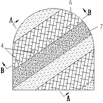
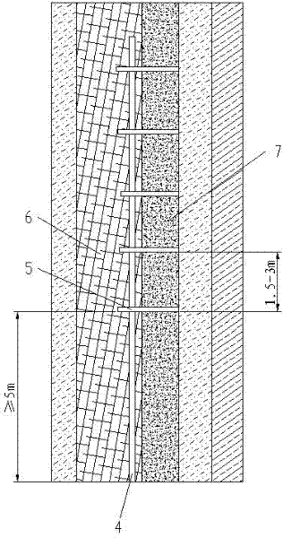
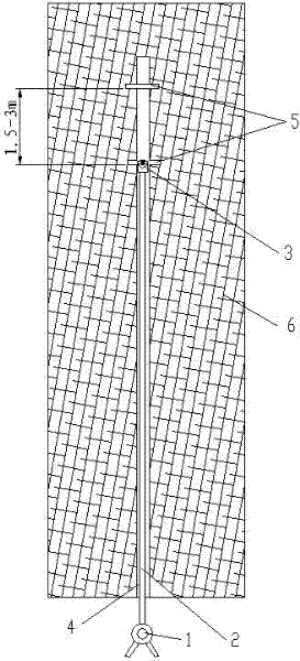
[0024] See figure 1 , figure 2 , image 3 , A pressure relief drainage method for cutting through the roof or floor of a coal seam by an abrasive jet, the method includes the following steps:
[0025] a. Use the drilling rig 1 to drill a bedding hole 4 to the set depth on the roof, floor or hard layer 6 of the coal rock mass in the semi-coal tunnel excavation through the drill pipe 2 and the slot drill bit 3;
[0026] b. Input a high-pressure abrasive water jet with a pressure of 25-30Mpa to the slot drill bit 3 through the drill pipe 2 and the drill pipe 2 rotates in situ, and a radial cut is formed on the hole wall of the layered borehole 4 through the high-pressure abrasive water jet. Seam 5. Slotted seam 5 penetrates the roof, floor or hard layer 6 and soft layer 7 of coal rock mass;
[0027] c. The drill rod 2 quickly moves back 1.5~3m to form a new slot 5;
[0028] d. Repeat step c until multiple radial slits 5 are formed on the layer-by-layer drilling 4, and the slits 5 located at the opening of the layer-by-layer drilling 4 have a set distance from the orifice, so that the layer-by-layer drilling A safety rock pillar of at least 5m is left at the mouth of hole 4;
[0029] e. Stop the high-pressure abrasive water jet, exit the drill pipe 2 and the slotted drill bit 3, and use the sealing material to seal the bedding drill 4 for more than 5m;
[0030] f. Use the gas drainage system to extract gas.
[0031] See Figure 4 Steps a to f are repeated to form two or more bedding boreholes 4 on the roof, floor or hard layer 6 of the coal rock mass, and the slits 5 formed on the adjacent bedding boreholes 4 are roughly equidistantly displaced.
[0032] The abrasive is 70-110 mesh quartz sand, and the abrasive accounts for 5% of the volume in the jet mixture.
[0033] Although the embodiments of the present invention have been described above in conjunction with the accompanying drawings, those of ordinary skill in the art can also realize that various changes or modifications can be made within the scope of the appended claims, and these modifications and changes should be understood to be in the present invention. Within the scope and intention of the invention.

PUM

no PUM

Description & Claims & Application Information

We can also present the details of the Description, Claims and Application information to help users get a comprehensive understanding of the technical details of the patent, such as background art, summary of invention, brief description of drawings, description of embodiments, and other original content. On the other hand, users can also determine the specific scope of protection of the technology through the list of claims; as well as understand the changes in the life cycle of the technology with the presentation of the patent timeline. Login to view more.

Similar technology patents

Classification and recommendation of technical efficacy words

Why Eureka
Try Eureka