Single-cable-replaceable type anchorage pre-stressed anchor device and installation and cable replacement methods thereof

An anchoring device and replaceable technology, applied in the direction of suspension bridges, bridge forms, bridge parts, etc., can solve the problems of increasing operation and maintenance costs, grease leakage of anchoring systems, and insufficient understanding of sealing performance, so as to solve the problems of beam penetration and sealing Can not take into account, the construction is convenient, the effect of preventing leakage

Active Publication Date: 2015-02-25
LIUZHOU OVM MACHINERY
View PDF9 Cites 11 Cited by
  • Summary
  • Abstract
  • Description
  • Claims
  • Application Information

AI Technical Summary

Problems solved by technology

The main defects are as follows: the construction technology is high, and the grease poured into the prestressed channel of the replaceable anchor system is in liquid state at present, the purpose is to facilitate the pouring and future grease replacement; but in this way, the tightness of the system High requirements are put forward for the construction. If there is a slight construction operation or inspection is not in place, the grease in the system will l

Method used


Image

  • Single-cable-replaceable type anchorage pre-stressed anchor device and installation and cable replacement methods thereof
  • Single-cable-replaceable type anchorage pre-stressed anchor device and installation and cable replacement methods thereof
  • Single-cable-replaceable type anchorage pre-stressed anchor device and installation and cable replacement methods thereof

Examples


Example Embodiment

[0053] Embodiment one:

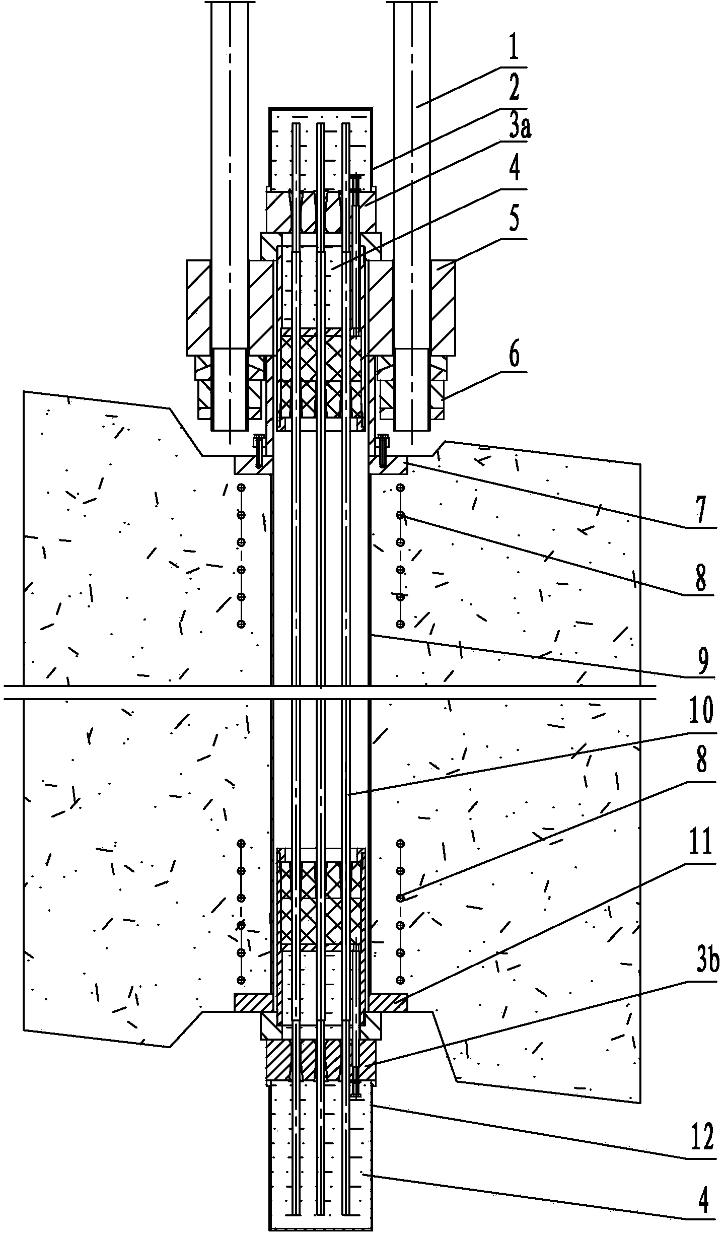
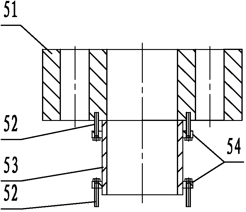
[0054] A single replaceable anchor prestressed anchoring device, such as figure 1 As shown, the single replaceable anchor prestressed anchoring device includes a pull rod 1, a front protective cover 2, an anchor assembly 3, a connector 5, a pull rod nut assembly 6, a front anchor plate 7, a spiral rib 8, a pre-embedded Pipe 9, unbonded PE steel strand 10, rear anchor plate 11 and rear protective cover 12;

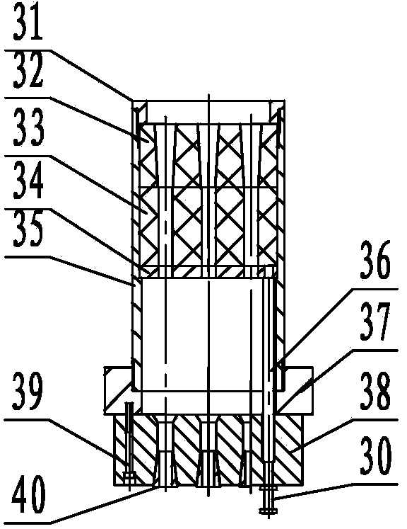
[0055] The anchor assembly 3 has two sets, namely the front anchor assembly 3a and the rear anchor assembly 3b, and each set of anchor assemblies consists of a gland 31, an outer sealing plate 32, an inner sealing plate 33, and a positioning plate 34 connected in sequence. , sealing cylinder 35, ejector rod 36, backing plate 37, anchor plate 38, bolt 39, screw rod 30 and working clip 40, outer sealing plate 32 and inner sealing plate 33 constitute the sealing device of the anchorage assembly, positioning plate 34 and The sealing cavity of the anch...

Example Embodiment

[0064] Embodiment two:

[0065] A method of installation and construction of a single replaceable anchor prestressed anchorage device, the replaceable anchor prestressed anchorage device is the single replaceable anchor prestressed anchorage device described in Embodiment 1, which The installation construction method includes the following steps:

[0066] Step 1: Install the embedded parts: pre-embed the rear anchor plate 11, spiral reinforcement 8, embedded pipe 9 and front anchor plate 7 at the construction site and pour concrete, and then maintain the concrete to the design strength;

[0067] Step 2: Install the connector: at the front anchor, use the bolt 52 to install the connector 5 on the front anchor plate 7;

[0068] Step 3: Install the anchor assembly: at the front anchor, install the front anchor assembly 3a on the end face of the connector 5; at the rear anchor, temporarily place the rear anchor assembly 3b directly under the rear anchor pad 11;

[0069] Step 4: ...

Example Embodiment

[0075] Embodiment three:

[0076] A cable replacement construction method for a single replaceable anchorage prestressed anchorage device, the replaceable anchorage prestressed anchorage device is the single replaceable anchorage prestressed anchorage device described in Embodiment 1, Its cable-changing construction method comprises the following steps:

[0077] Step 1: Remove the front protective cover 2 and the rear protective cover 12, remove the non-drying anti-corrosion material 4 on the anchor plate 38, and loosen the screw 30;

[0078] Step 2: At the rear anchor, use a single tension jack to unload the unbonded PE steel strand 10 to be replaced, and take out the working clip 40 from the rear anchor plate 38;

[0079] Step 3: At the rear anchor, connect the old and new strands with strand connectors;

[0080] Step 4: At the front anchor, use a single tension jack to unload the unbonded PE steel strand 10 to be replaced, and pull out the old steel strand upwards while i...


PUM


Abstract

A single-cable-replaceable type anchorage pre-stressed anchor device comprises a pull rod, a front protection cover, a rear protection cover, anchor gear assemblies, a connector, a pull rod nut assembly, a front anchor backing plate, a rear anchor backing plate, spiral ribs, an embedded pipe and unbonded PF steel strands. The connector is installed on the front anchor backing plate. The front anchor gear assembly is installed on the end face of the connector, and the rear anchor gear assembly is placed under the rear anchor backing plate. The two ends of each unbonded PF steel strand are removed, the remaining part of each unbonded PF steel strand is wrapped by PE, the exposed parts of the upper ends of the unbonded PF steel strands are located in a sealed cavity formed by an anchor plate of the front anchor gear assembly and the front protection cover and anchored to the anchor plate through working clamping pieces, and the exposed parts of the lower ends of the unbonded PF steel strands are located in a sealed cavity formed by an anchor plate of the rear anchor gear assembly and the rear protection cover and anchored to the anchor plate through working clamping pieces. By pressing and ejecting inner sealing plates and outer sealing plates through screw rods and ejector rods, the diameter of through holes in the inner sealing plate and through holes in the outer sealing plate can be adjusted. A sealed cavity of the front anchor gear assembly, a sealed cavity of the rear anchor gear assembly, the sealed formed by the front protection plate and the anchor plate of the front anchor gear assembly and the sealed cavity formed by the rear protection plate and the anchor plate of the rear anchor gear assembly are filled with non-drying anticorrosive materials. The anchor device is reliable in use and low in cost, and installation construction and cable replacement construction are convenient.

Description

technical field [0001] The invention relates to a prestressed anchoring device and its construction method, in particular to a single replaceable prestressed anchoring device and its construction method for the anchorage of a suspension bridge. Background technique [0002] The anchorage system of large suspension bridges mostly adopts prestressed anchorage system. The existing prestressed anchorage system has two forms, one is the bonded anchorage system in which grout is poured in the prestressed tunnel, the other is the An unbonded single-root replaceable anchor system that is filled with special anti-corrosion grease in the channel. The current unbonded single-root replaceable anchor system mainly uses galvanized steel strands and thin epoxy-coated steel strands as pre-installed anchorage systems. Stress tendons, among which thin epoxy-coated steel strands with relatively superior anti-corrosion performance are the main ones. [0003] The utility model patent "Prestress...

Claims


Application Information

Patent Timeline
IPC IPC(8): E01D19/14
CPCE01D11/02E01D19/14
Inventor 苏强常志军谢正元王茂强吴东明赵靖钊邓昱罗春林曾诚
Owner LIUZHOU OVM MACHINERY
Why Eureka
Try Eureka