Drilling machine for metal pipe tapping

A technology for metal pipes and drilling machines, which is applied in the direction of boring/drilling, metal processing equipment, drilling/drilling equipment, etc. It can solve the problems of poor pipeline firmness, low drilling efficiency, and affecting drilling quality, etc., to achieve Easy to adjust position and improve drilling efficiency

Inactive Publication Date: 2017-09-15
惠安县长信机电科技有限公司
View PDF6 Cites 32 Cited by
  • Summary
  • Abstract
  • Description
  • Claims
  • Application Information

AI Technical Summary

Problems solved by technology

[0003] As a type of pipeline, metal pipes often need to be drilled due to the needs of practical applications. There are currently two types of pipeline drilling methods. One is that the operator fixes the pipeline by pressing with his hands, and manually Electric drills perforate metal pipes. This method is not fast enough to fix the pipes, and the pipes are prone to rolling and slipping during the drilling process. Not only will the perforation position shift and affect the drilling quality, but the drill bit is easy to drill. The other is to use mechanical drilling equipment to drill metal pipes. However, in actual use, it is often necessary to drill multiple holes on the side of the metal pipe, and the pipe needs to be rotated. The clamping device of the existing drilling machine is not convenient enough for the rotation of the pipeline, resulting in low drilling efficiency; at the same time, it is easy to cause the drill to heat up during the drilling process, and the lack of cooling function will easily cause damage to the drill bit and affect the drilling quality

Method used


Image

  • Drilling machine for metal pipe tapping
  • Drilling machine for metal pipe tapping
  • Drilling machine for metal pipe tapping

Examples


Embodiment Construction

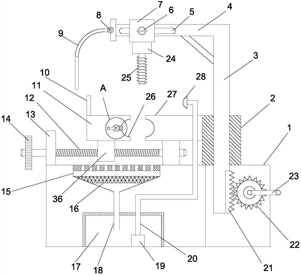
[0025] Below in conjunction with specific embodiment, the technical scheme of this patent is described in further detail:

[0026] see Figure 1-5 , a drilling machine for drilling metal pipes, comprising a body 1, characterized in that, the bottom of the body 1 is provided with a liquid storage tank 17, and the liquid storage tank 17 is filled with cooling liquid; the body 1 is provided with a sleeve 2, the sleeve A column 3 is slidably installed on the tube 2, a spur rack 21 is provided at the bottom of the column 3, a drive gear 22 is provided on the right side of the column 3, the drive gear 22 is meshed with the spur rack 21, and the drive gear 22 is fixedly installed with a first Rocker 23; the left side of the sleeve 2 is fixedly equipped with a right pressure block 27, the body 1 is fixedly equipped with a support 13, the support 13 is horizontally provided with a lead screw 12, the left end of the lead screw 12 is fixedly equipped with a hand wheel 14, and The bar 12...


PUM


Abstract

The invention discloses a drilling machine for metal pipe tapping. The drilling machine comprises a main body; a sleeve is arranged on the main body; a stand column is slidingly mounted on the sleeve; a straight rack is arranged at the lower part of the stand column; a driving gear is arranged on the right side of the stand column; a right pressing block is fixedly mounted on the left side of the sleeve; a bracket is fixedly mounted on the main body; a lead screw is horizontally arranged on the bracket; a hand wheel is fixedly mounted at the left end of the lead screw; a sleeve block sleeves the lead screw; arc grooves are respectively formed in the right side surface of the left pressing block and the left side surface of the right pressing block; a leakage pipe is arranged at the bottom of a liquid collecting tank, and extends into a liquid storage box; a conveying pimp is arranged at the bottom of the liquid storage box; a conveying pipe is arranged at an outlet end of the conveying pump; and a nozzle is arranged at one end, far from the conveying pump, of the conveying pipe. A metal pipe is driven to rotate through rotation of a rotating roller, so that multiple places of the side surface of the pipe are conveniently drilled, and the drilling efficiency is improved; cooling liquid sprayed by the nozzle can cool a drill bit to prevent damage of the drill bit due to overheating; and meanwhile, the cooling liquid can be recycled, so that the waste of the cooling liquid is prevented.

Description

technical field [0001] The invention relates to the technical field of pipeline manufacturing and processing, in particular to a drilling machine for drilling metal pipelines. Background technique [0002] A pipeline is a device connected by pipes, pipe connectors and valves to transport gas, liquid or fluid with solid particles. Due to its unique characteristics, pipelines are widely used in many industries and fields. Pipes are widely used, mainly in water supply, drainage, heat supply, gas supply, long-distance transportation of oil and natural gas, agricultural irrigation, hydraulic engineering and various industrial devices. [0003] As a type of pipeline, metal pipes often need to be drilled due to the needs of practical applications. There are currently two types of pipeline drilling methods. One is that the operator fixes the pipeline by pressing with his hands, and manually Electric drills perforate metal pipes. This method is not fast enough to fix the pipes, and ...

Claims


Application Information

Patent Timeline
Patent Type & Authority Applications(China)
IPC IPC(8): B23B39/00B23Q3/06B23Q11/10
CPCB23B39/00B23Q3/064B23Q11/10
Inventor 不公告发明人
Owner 惠安县长信机电科技有限公司
Why Eureka
Try Eureka