
Temperature control valve element

A technology of temperature control valve and valve stem, which is applied in the field of faucet spool, can solve the problems of large volume, complex structure of thermostatic faucet, high manufacturing cost, etc., and achieve the goal of avoiding excessive volume, avoiding too complicated internal structure and reducing production cost Effect

Active Publication Date: 2015-12-23
HESHAN LE BAIN TEMPERATURE CONTROL BATHROOM CO LTD
View PDF4 Cites 8 Cited by
  • Summary
  • Abstract
  • Description
  • Claims
  • Application Information

AI Technical Summary

Problems solved by technology

[0004] Whether the temperature control valve core mentioned above is a temperature control ceramic valve core controlled by a rotary knob or a temperature control valve core controlled by a thermal element, when used as a temperature control valve core of a thermostatic faucet, it cannot achieve temperature regulation and at the same time achieve waterway protection. On-off control, generally speaking, an on-off spool should be installed at the other end of the thermostatic faucet to cooperate with the temperature-control spool. Cold water and hot water must pass through the on-off spool and then flow into the temperature-control spool for mixing and temperature adjustment. All thermostatic faucets have complex structures, large volumes, and high manufacturing costs. On the other hand, it is very inconvenient for users to adjust the temperature control valve core while adjusting the switch valve core.

Method used


Image

  • Temperature control valve element
  • Temperature control valve element
  • Temperature control valve element

Examples


Embodiment Construction

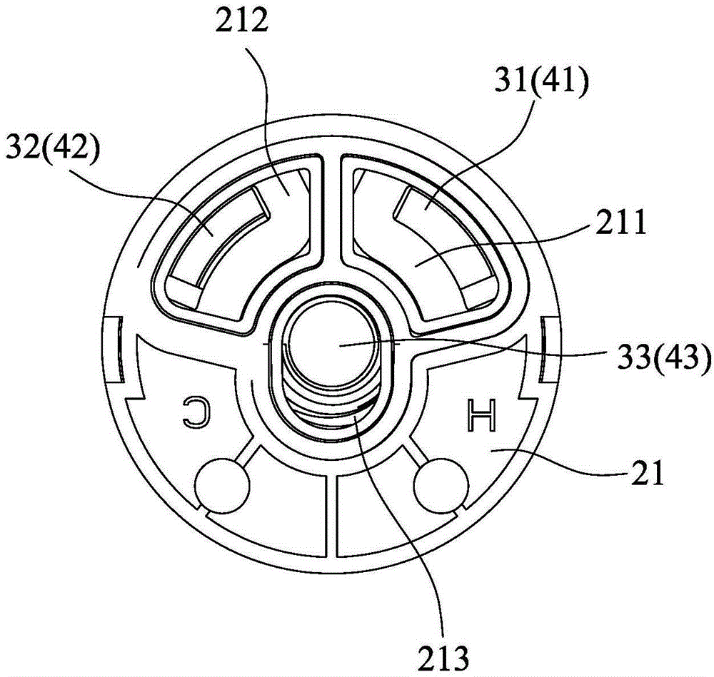
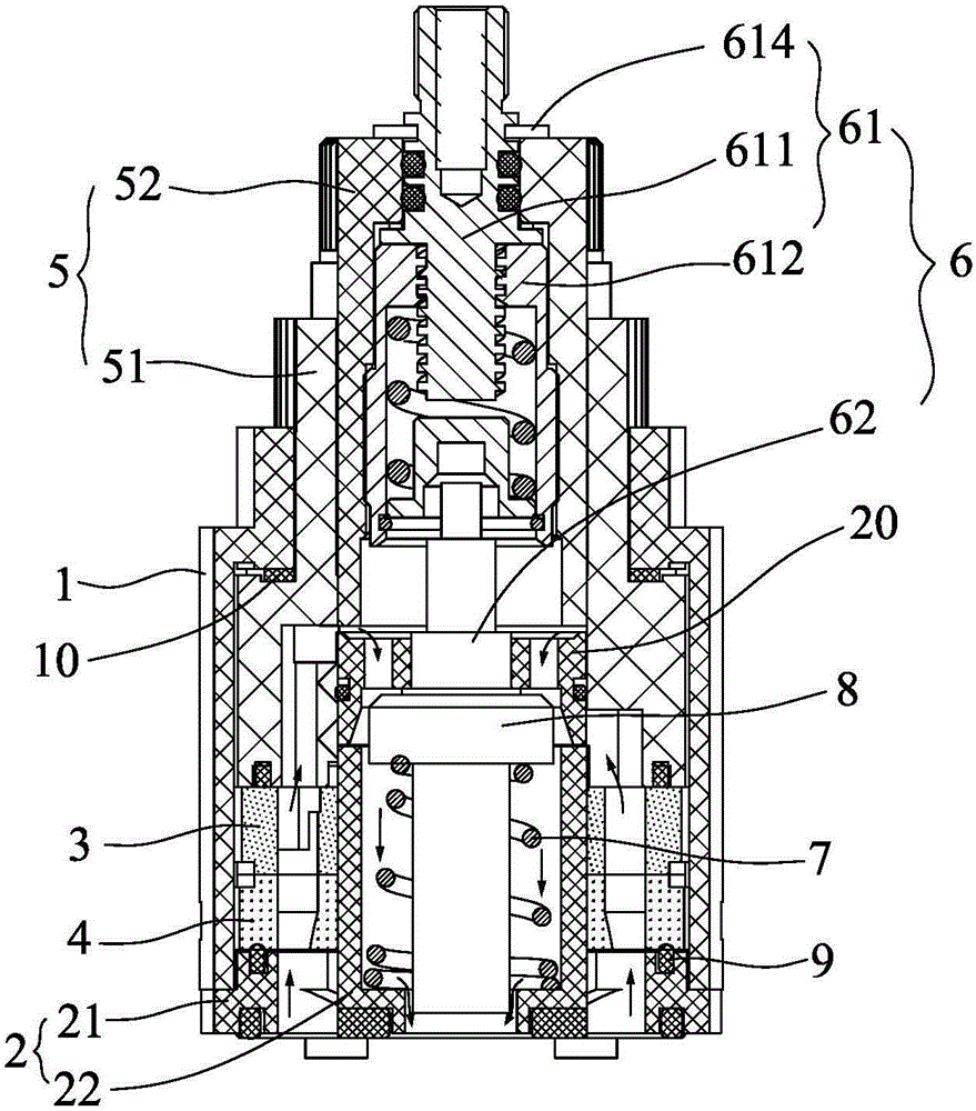
[0035] Such as Figure 1 to Figure 9 As shown, the temperature control valve core disclosed by the present invention includes:

[0036] A housing 1, forming an accommodating space 11 in the housing 1;

[0037] Base 2, the base 2 is socketed on the bottom of the housing 1, and the base 2 is provided with a hot water inlet, a cold water inlet and a mixed water outlet; specifically, the base 2 includes a seat body 21, and the seat body 21 and the bottom end of the housing 1 For docking, the seat body 21 is provided with a hot water inlet 211 , a cold water inlet 212 and a mixed water outlet 213 , and a spacer 22 extends upward from the periphery of the seat body mixed water outlet 213 .

[0038] The moving ceramic sheet 3 and the static ceramic sheet 4 are all socketed in the accommodation space of the housing 1, the moving ceramic sheet 3 is docked with the base 2, and the moving ceramic sheet 3 and the static ceramic sheet 4 tight fit; the moving ceramic sheet 3 and the static ...


PUM


Abstract

The invention discloses a temperature control valve element. The temperature control valve element comprises a shell with containing space, a base, a movable ceramic piece, a fixed ceramic piece, a first rotary adjusting assembly and a second rotary adjusting assembly; the bottom end of the shell is sleeved with the base in a connected manner, and a hot water inlet, a cold water inlet and a mixed water outlet are formed in the base; the movable ceramic piece and the fixed ceramic piece are both sleeved with the containing space of the shell in a connected manner, the movable ceramic piece is in butt joint with the base, and the movable ceramic piece and the fixed ceramic piece are in tight fit; the movable ceramic piece and the fixed ceramic piece are each provided with a hot water inlet through hole, a cold water inlet through hole and a mixed water outlet through hole; the first rotary adjusting assembly is sleeved with the containing space in the top of the shell in a connected manner in the manner of being capable of rotating in the axial direction, and the bottom of the first rotary adjusting assembly is connected with the movable ceramic piece in a clamped manner; and the second rotary adjusting assembly comprises a pushing component, a valve rod and an elastic recovery element. Temperature adjustment, flow adjustment and switch control can be achieved, an extra switching valve element is omitted, the problem that an internal structure of a constant-temperature faucet is too complex and too large in size is solved, and the production cost is reduced.

Description

technical field [0001] The invention relates to a valve core of a faucet, in particular to a temperature control valve core. Background technique [0002] In a constant temperature water faucet, the temperature control valve core is a key component to achieve a constant water temperature. The temperature control valve core of an existing faucet mainly includes a housing, a rotating core, a moving ceramic piece, and a static ceramic piece. Space, the dynamic ceramic piece and the static ceramic piece are both socketed in the accommodation space at the lower end of the shell, the static ceramic piece is fixedly arranged under the moving ceramic piece, there are two opposite water inlet holes on the static valve piece, and the moving ceramic piece There is a water outlet hole corresponding to the water inlet hole, the rotating core is sleeved in the accommodation space at the upper end of the housing, and the lower end of the rotating core is clamped on the moving ceramic piece...

Claims


Application Information

Patent Timeline
Patent Type & Authority Applications(China)
IPC IPC(8): F16K11/074F16K3/30F16K3/32
CPCF16K3/30F16K3/32F16K11/074
Inventor 刘兆祥
Owner HESHAN LE BAIN TEMPERATURE CONTROL BATHROOM CO LTD
Learn More