
Air supply device

A technology of air supply device and control device, which is applied in the direction of ventilation system, space heating and ventilation, space heating and ventilation details, etc. It can solve the problems of impurities in the air inlet cavity, and achieve the effect of improving cleanliness and waterproofing

Inactive Publication Date: 2015-12-23
广州市雷子克电气机械有限公司
View PDF8 Cites 3 Cited by
  • Summary
  • Abstract
  • Description
  • Claims
  • Application Information

AI Technical Summary

Problems solved by technology

However, the output airflow of the existing air supply device is often accompanied by a large amount of dust and water vapor, thereby bringing a large amount of impurities to the air inlet cavity.

Method used


Image

  • Air supply device
  • Air supply device

Examples


Embodiment Construction

[0017] Hereinafter, the present invention will be further described with reference to the drawings and specific implementations:

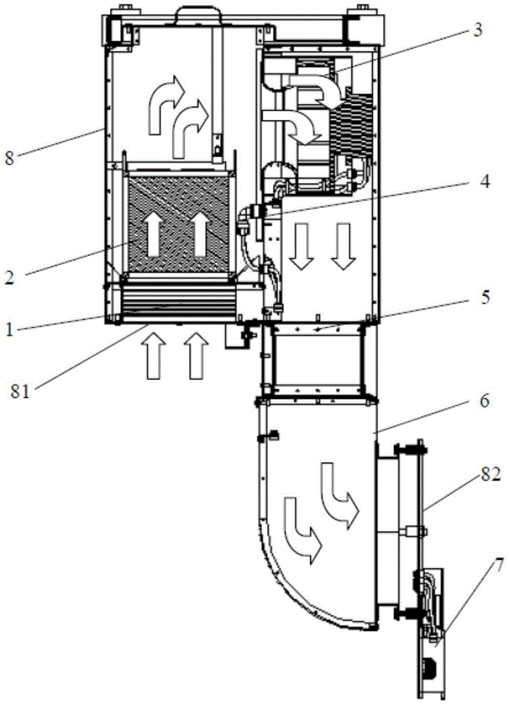
[0018] Such as figure 1 As shown, the air supply device of the present invention includes a housing 8 provided with an air inlet 81 and an air outlet 82; the air inlet 81 of the housing 8 faces downward; the inner edge of the housing 8 A demister 1, a filter 2, and a fan 3 are arranged in the direction from the air inlet 81 to the air outlet 82; the fan 3 is used to drive the air flow from the air inlet 81 to the air outlet 82.

[0019] The working process of the present invention is as follows: the fan 3 works, the airflow flows in from the air inlet 81, and then flows through the demister 1. The demister 1 can be used to separate the airflow from water vapor to remove the water vapor entrained in the airflow, and then flow through The filter 2 can use the filter 2 to filter the airflow, then flow through the fan 3, and finally flow out from the air ou...


PUM


Abstract

The invention discloses an air supply device. The air supply device comprises a shell which is provided with an air inlet and an air outlet; the air inlet of the shell faces downwards; a demister, a filter and a draught fan are sequentially arranged in the shell in the direction from the air inlet to the air outlet; the draught fan is used for driving airflow to flow from the air inlet to the air outlet. According to the air supply device, due to the fact that the orientation of the air inlet is reasonably arranged, the phenomenon that steam and dust enter the shell can be reduced, and the effects of resisting water and dust are improved; in addition, by means of the design of combining the demister, the filter and the draught fan, the dust and the steam which are carried by the output airflow can be reduced; by means of the design of combining a pressure difference transducer, a warning device and a control device, the blocking condition of the filter can be monitored, and a user is reminded to replace the filter through the warning device. In addition, according to the air supply device, the working condition of the draught fan can be controlled according to the temperature of an air inlet cavity, and the purpose of achieving intelligence and energy conservation can be achieved.

Description

Technical field [0001] The invention relates to an air supply device. Background technique [0002] The air supply device is often used to supply air to the outside air inlet cavity (wherein, the air inlet cavity can be a cavity provided on the mechanical equipment to be cooled, or an indoor room to be ventilated and dissipated) to provide ventilation and heat dissipation effect. However, a large amount of dust and water vapor are often attached to the output air flow of the existing air supply device, thereby bringing a large amount of impurities to the air inlet cavity. Summary of the invention [0003] In order to overcome the shortcomings of the prior art, the purpose of the present invention is to provide an air blowing device that can reduce dust and water vapor accompanying the output airflow. [0004] To solve the above-mentioned problems, the technical solutions adopted by the present invention are as follows: [0005] The air supply device includes a housing, the housing ...

Claims


Application Information

Patent Timeline
IPC IPC(8): F24F7/08F24F13/28F24F3/14F24F11/02
CPCF24F3/14F24F7/08F24F11/0001F24F11/30F24F11/39F24F11/46F24F11/62F24F2110/00F24F8/10F24F8/108
Inventor 周钰铭
Owner 广州市雷子克电气机械有限公司
Learn More