A pulse filter circuit and method thereof

A filter circuit and pulse filtering technology, applied in pulse technology, pulse processing, electrical components, etc., can solve problems such as narrow pulse distortion, and achieve the effect of avoiding strict requirements and avoiding narrow pulse distortion.

Active Publication Date: 2018-08-03
SICHUAN YICHONG TECH CO LTD
View PDF4 Cites 0 Cited by
  • Summary
  • Abstract
  • Description
  • Claims
  • Application Information

AI Technical Summary

Problems solved by technology

[0006] The purpose of the present invention is to provide a pulse filter circuit and method for the above-mentioned shortcomings in the prior art, which can transmit any pulse signal larger than the set width without distortion, avoiding the problem of narrow pulse distortion in traditional circuits, Therefore, it is necessary to make the filtered time before reaching the positive increasing threshold of the Schmitt trigger during the capacitor charging process and the extra time before reaching the negative decreasing threshold during the capacitor discharging process exactly equal; it is also necessary to use any threshold value. Mitt trigger, avoiding the strict requirements on the Schmitt trigger threshold in traditional circuits

Method used


Image

  • A pulse filter circuit and method thereof
  • A pulse filter circuit and method thereof
  • A pulse filter circuit and method thereof

Examples


Embodiment Construction

[0029] The technical solutions of the present invention will be described in further detail below with reference to the accompanying drawings and embodiments.

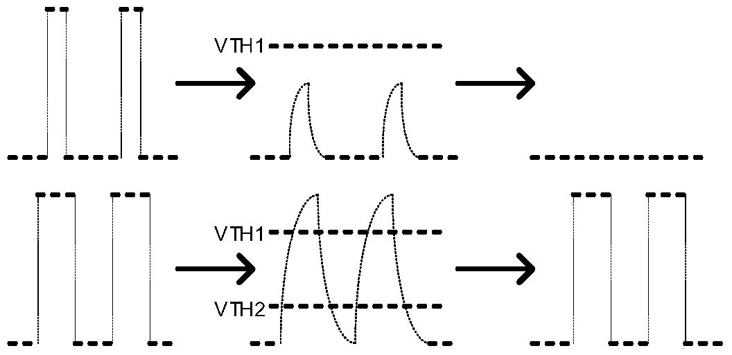
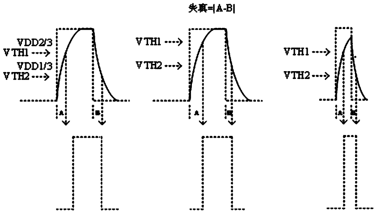
[0030] A pulse filter circuit and method claimed in the present invention can transmit any pulse signal larger than the set width without distortion, thereby avoiding the problem of narrow pulse distortion in traditional circuits, and can use any threshold Schmitt trigger device, thereby avoiding the strict requirement on the Schmitt trigger threshold in traditional circuits.

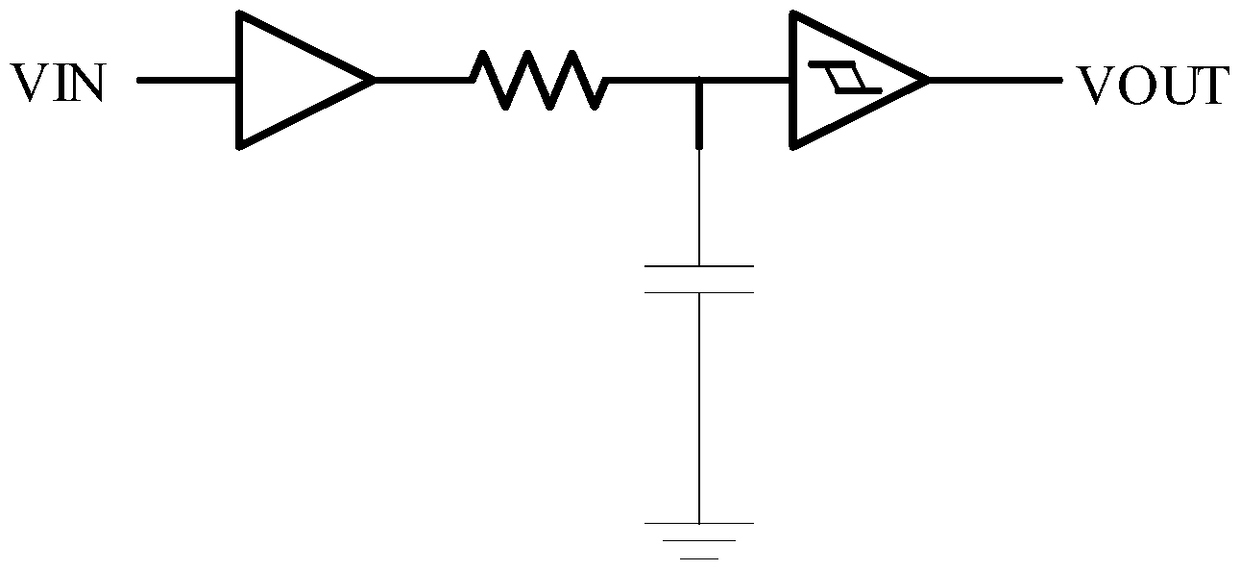
[0031] Figure 4 A schematic structural diagram of a pulse filter circuit provided by Embodiment 1 of the present invention. Such as Figure 4 As shown, the circuit includes: a receiving circuit 001, a filter circuit 002 and an output and feedback circuit 003, wherein the receiving circuit 001 is used to receive pulse signals, and the pulse signals include positive pulses and negative pulses; the filter circuit 002 is used to detect the The w...


PUM


Abstract

The present invention relates to a pulse filter circuit and a method thereof, wherein the pulse filter circuit comprises: a receiving circuit (001) for receiving a pulse signal; a filter circuit (002) for detecting the width of the pulse signal; output and feedback The circuit (003) is used to output a feedback control signal to the filter circuit (002) according to the width of the pulse signal, and adjust the output pulse signal to be in phase with the pulse signal and output it; the filter circuit (002) is set according to the feedback control signal Determine the width of the pulse signal. The invention can transmit any pulse signal larger than the set width without distortion, avoids the problem of narrow-wave pulse distortion in traditional circuits, and has important application value in the field of analog circuit design.

Description

technical field [0001] The invention relates to the field of analog circuit design, in particular to a pulse filter circuit and a method thereof. Background technique [0002] Input pulse signal filtering is an important function in the circuit system, which has a great influence on the performance and reliability of the system. [0003] figure 1 It is a schematic structural diagram of a simple pulse filter circuit in the prior art. Such as figure 1 As shown, the circuit is composed of a non-inverter, an RC filter circuit, and a Schmitt trigger, and the power supply of the circuit is VDD. This structure can filter out the noise below the fixed pulse width through the RC structure and the Schmitt trigger. The principle is that the input signal passes through the non-inverter to control the charging and discharging of the capacitor. When the input signal pulse width is narrow, the capacitor cannot be charged to When it is enough to make the Schmitt trigger flip, the output...

Claims


Application Information

Patent Timeline
Patent Type & Authority Patents(China)
IPC IPC(8): H03K5/1252
Inventor 迟明潘建斌
Owner SICHUAN YICHONG TECH CO LTD
Why Eureka
Try Eureka