
A led drive circuit

A circuit and main circuit technology, applied in the circuit field, can solve problems such as LED load flickering or flickering, achieve the effect of solving flickering or flickering, increasing hiccup frequency, and reducing current ripple

Active Publication Date: 2018-05-01
INVENTRONICS HANGZHOU
View PDF5 Cites 0 Cited by
  • Summary
  • Abstract
  • Description
  • Claims
  • Application Information

AI Technical Summary

Problems solved by technology

[0005] This application provides an LED drive circuit. In the hiccup mode, when the LED load is light, the hiccup frequency can be increased, so that the current ripple output by the LED driver becomes smaller, thereby solving the problem of flickering or flickering of the LED load

Method used


Image

  • A led drive circuit
  • A led drive circuit
  • A led drive circuit

Examples


Embodiment Construction

[0051] The following will clearly and completely describe the technical solutions in the embodiments of the application with reference to the drawings in the embodiments of the application. Apparently, the described embodiments are only some of the embodiments of the application, not all of them. Based on the embodiments in this application, all other embodiments obtained by persons of ordinary skill in the art without making creative efforts belong to the scope of protection of this application.

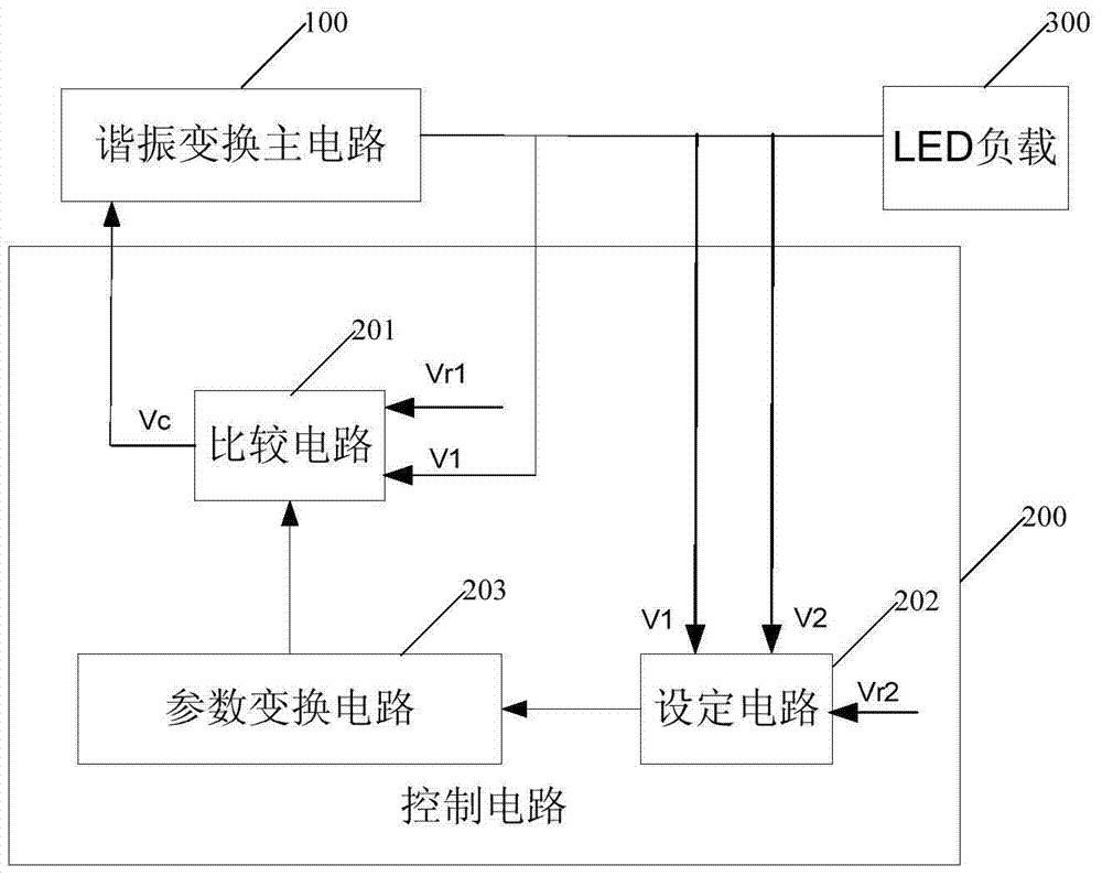
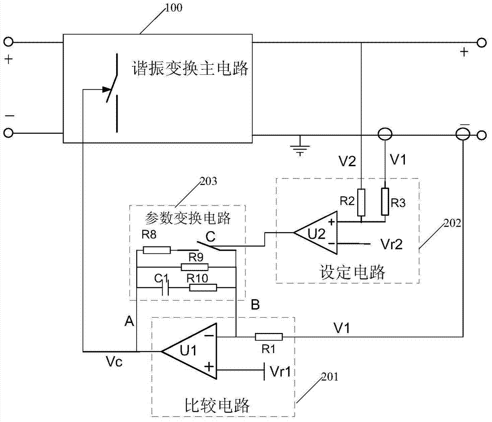
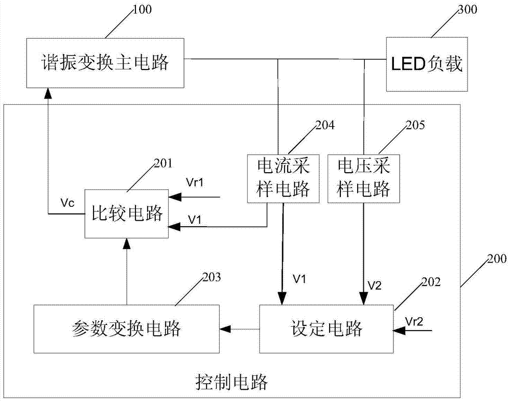
[0052] Such as figure 1 As shown, the present application provides an LED driving circuit, including: a resonant conversion main circuit 100 and a control circuit 200 . The control circuit 200 includes: a comparison circuit 201 , a setting circuit 202 and a parameter conversion circuit 203 .

[0053] The resonant conversion main circuit in this application can be any resonant conversion circuit controlled by frequency conversion, such as LLC resonant conversion circuit, LCC resonan...


PUM


Abstract

The present application provides an LED driving circuit, which is characterized in that it includes: a resonant conversion main circuit and a control circuit; wherein, the control circuit includes: a comparison circuit, a setting circuit and a parameter conversion circuit. The control circuit detects the output current and output voltage of the resonant conversion main circuit, and superimposes the output current and output voltage in the setting circuit as the current superimposed value. According to the relationship between the current superimposed value and the reference superimposed value, it is determined that the parameter conversion circuit is in the fast loop. loop state or slow loop state, and then control the response speed of the comparison circuit outputting the control signal. In this way, when the output current is small and the output voltage is low, if the resonant conversion main circuit enters the hiccup mode, the control circuit can quickly respond to the resonant conversion main circuit output voltage and output current, thereby increasing the hiccup frequency and reducing the output of the resonant conversion main circuit. Current ripple, so as to solve the stroboscopic or flickering phenomenon of the LED load connected to the LED driver.

Description

technical field [0001] The present application relates to the field of circuit technology, in particular to an LED driving circuit. Background technique [0002] At present, as a new type of lighting device, LED is widely promoted in the field of lighting due to its advantages of high luminous efficiency, long life and no pollution. In the process of using the LED, an LED driver is required to drive the LED to emit light. Among them, medium and high-power LED drivers often use high-efficiency resonant conversion topology as the conversion of DC / DC constant current control. [0003] The LED driver includes a resonant conversion main circuit and a control circuit. Generally, the operating frequency of the resonant conversion main circuit is inversely proportional to the change of the LED load, that is, the lighter the LED load, the higher the operating frequency of the resonant conversion main circuit. However, the operating frequency of the resonant conversion main circuit...

Claims


Application Information

Patent Timeline
Patent Type & Authority Patents(China)
IPC IPC(8): H05B37/02
Inventor 俞杭冬
Owner INVENTRONICS HANGZHOU
Learn More