

Liquid crystal drive circuit
A liquid crystal drive circuit, liquid crystal technology, applied to instruments, static indicators, etc., can solve problems such as incorrect voltage control, image quality degradation, etc.
- Summary
- Abstract
- Description
- Claims
- Application Information
AI Technical Summary
Problems solved by technology
Method used
Image

Examples
Embodiment 1
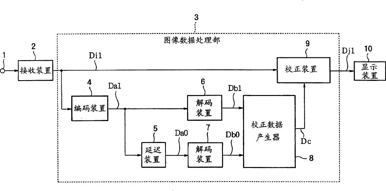
[0124] FIG. 2 is a diagram showing the configuration of a liquid crystal drive circuit in Embodiment 1. FIG. The receiving device 2 receives an image signal through the input terminal 1, and sequentially outputs current image data Di1 representing an image of one frame (hereinafter referred to as a current image). The image data processing unit 3 is composed of encoding means 4, delay means 5, decoding means 6, 7, correction data generator 8, and correction means 9, and generates new image data Di1 corresponding to the current image data Di1. The display device 10 is configured using a general liquid crystal display panel, and performs a display operation by applying a voltage corresponding to the tone value of an image to the liquid crystal.
[0125] The encoding device 4 outputs encoded data Da1 obtained by encoding the current image data Di1. The coding of the existing image data Di1 can use block coding such as FBTC or GBTC. Also, any coding method for still images such ...
Embodiment 2
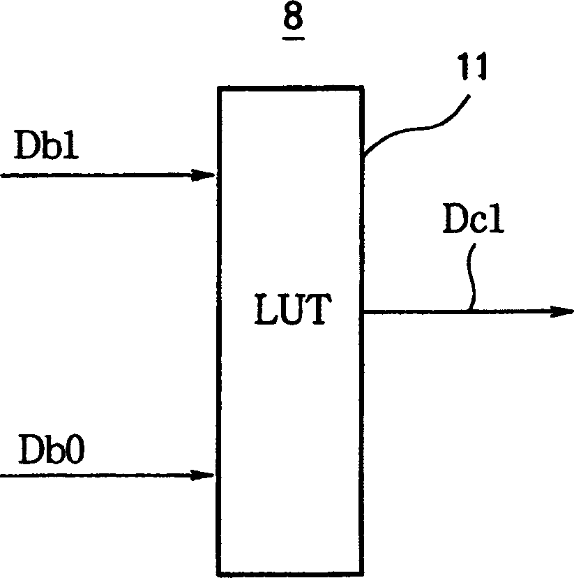
[0152] FIG. 13 is a diagram showing a first configuration of the correction data generator 8 of the second embodiment. The data conversion device 12 outputs new decoded image data De1 corresponding to the decoded image data Db1 by converting the number of quantization bits of the decoded image data Db1 from, for example, 8 bits to 3 bits. The look-up table 13 outputs correction data Dc1 based on the decoded image data De1 and the decoded image data Db0 after the digit conversion.
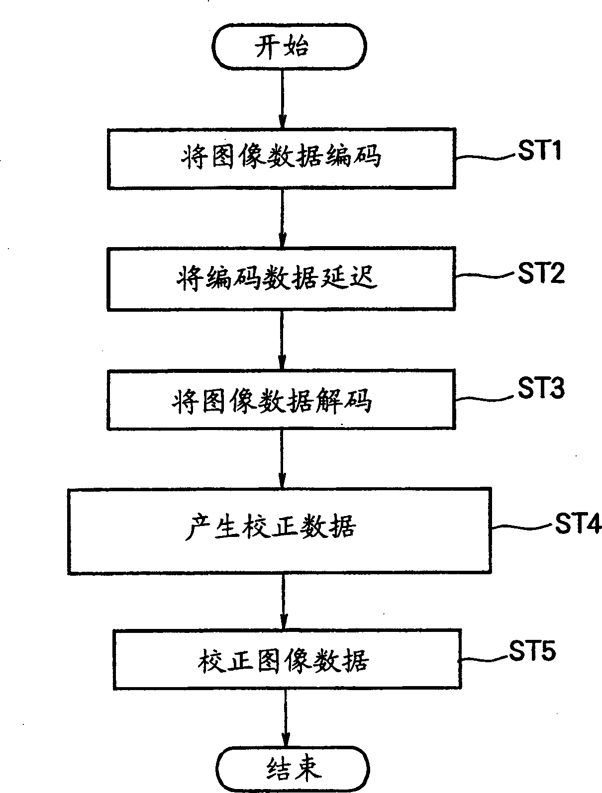
[0153] FIG. 12 is a flowchart showing the operation of the liquid crystal drive circuit having the correction data generator 8 shown in FIG. 13 . In the coded data conversion step ( St6 ), the number of quantization bits of the decoded image data Db1 is reduced by the data converter 12 . In the next corrected data generation step (St4), corrected data Dc1 is output based on the decoded image data De1 and decoded image data Db0 converted using the 13-bit lookup table. Operations in other steps are ...
Embodiment 3
[0169] FIG. 23 is a diagram showing a first configuration of a correction data generator of Embodiment 3. FIG. The data conversion device 17 linearly quantizes the decoded image data Db1 , converts the number of quantization bits from, for example, 8 bits to 3 bits, and outputs the decoded image data De1 after the bit number conversion. At the same time, the data conversion device 17 calculates an interpolation coefficient k1 to be described later. The look-up table 18 outputs two pieces of internal correction data Df1 and Df2 based on the decoded image data De1 after bit conversion and the 8-bit decoded image data Db0. The correction data interpolation device 19 generates the correction data Dc1 according to the two internal correction data Df1, Df2 and the interpolation coefficient k1.
[0170] FIG. 22 is a flowchart showing the operation of the liquid crystal drive circuit of this embodiment having the correction data generator 8 shown in FIG. 23 . In the coded data conve...
PUM
 Abstract
Description
Claims
Application Information