Variable-magnification observation optics
An optical system and low magnification technology, applied in the field of variable magnification observation optical systems, can solve the problems of complex mechanical structure, increased weight of the moving group, and difficulty in realizing the overall lightweight of the unit.
Active Publication Date: 2015-12-23
KONICA MINOLTA INC
View PDF6 Cites 3 Cited by
- Summary
- Abstract
- Description
- Claims
- Application Information
AI Technical Summary
Problems solved by technology
[0005] In Embodiment 1 of Patent Document 1, the moving group is composed of a plurality of lenses, so the weight of the moving group increases and the mechanical structure becomes complicated
Therefore, it is difficult to reduce the weight of the whole unit
In Example 2 of Patent Document 1, the group closest to the pupil in the eyepiece system is composed of only a pair of cemented lenses, so it is difficult to simultaneously and satisfactorily correct aberrations in the central portion and the peripheral portion
Method used
View moreImage
Smart ImageViewing Examples


Examples
Embodiment 1
[0144] Unit: mm
[0145] surface data
[0146]
[0147] Aspheric Data
[0148]
[0149] various data
[0150]
Embodiment 2
[0152] Unit: mm
[0153] surface data
[0154]
[0155] Aspheric Data
[0156]
[0157] various data
[0158]
Embodiment 3
[0160] Unit: mm
[0161] surface data
[0162]
[0163] Aspheric Data
[0164]
[0165] various data
[0166]
Login to View More PUM
 Abstract
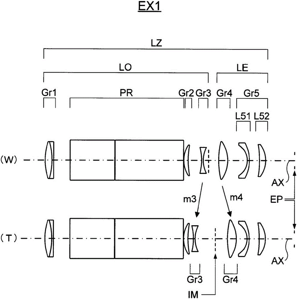
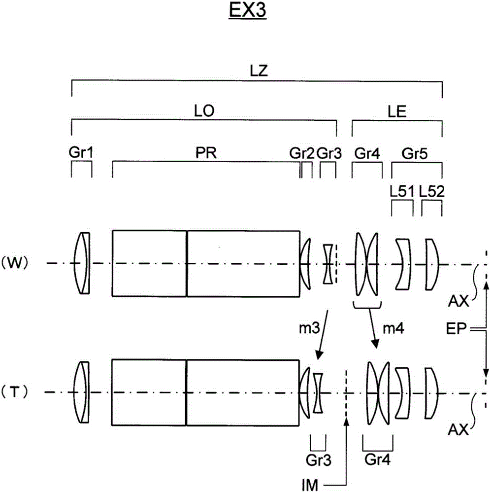
These variable-magnification observation optics are provided with an objective system, an erecting system, and an eyepiece system. In order from the object side, the objective system comprises a positive first group, a positive second group, and a negative third group. In order from the object side, the eyepiece system comprises a positive fourth group and a positive fifth group. The erecting system is located between the first and second groups. In order from the object side, the fifth group comprises a negative meniscus lens, the concave surface of which faces the object side, and a positive lens, with an air gap therebetween. The fifth group has at least one aspheric surface.
Description
technical field [0001] The present invention relates to a variable magnification observation optical system, for example, relates to a variable magnification observation optical system used in medical magnifiers, work magnifiers, binoculars, ground telescopes and the like. Background technique [0002] In observation optical systems used in magnifying glasses, binoculars, ground telescopes, etc., conventionally, a reverse erecting system such as a prism is used to invert the inverted image formed by the objective lens system into an erected image, and observe the image through the eyepiece system. The so-called Keplerian type (real image type) of the type. In addition, a zoom optical system having a zoom ratio of about 2x is easy to downsize, so as proposed in Patent Document 1, a zoom type that performs zooming with a pair of lenses sandwiching the above-mentioned inverted image is generally employed. [0003] For example, in Example 1 of Patent Document 1, for the purpose...
Claims
Login to View More Application Information
Patent Timeline
 IPC IPC(8): G02B25/00G02B23/02
CPCG02B25/001G02B13/18G02B15/143103G02B15/145127G02B23/2423G02B27/0025
Inventor 神诚
Owner KONICA MINOLTA INC
Features
- R&D
- Intellectual Property
- Life Sciences
- Materials
- Tech Scout
- Unparalleled Data Quality
- Higher Quality Content
- 60% Fewer Hallucinations
Learn More Browse by: Latest US Patents, China's latest patents, Technical Efficacy Thesaurus, Application Domain, Technology Topic, Popular Technical Reports.
© 2025 PatSnap. All rights reserved.Legal|Privacy policy|Modern Slavery Act Transparency Statement|Sitemap|About US| Contact US: help@patsnap.com