
Side edge punching mold

A die and punching technology, applied in the field of side punching die, can solve the problems of punch and concave die gnawing, chipping, the impact of die mass production, etc., to ensure the effect of life and stability.

Inactive Publication Date: 2015-12-30
WUXI MICRO RES PRECISION PRESS PARTS
View PDF8 Cites 2 Cited by
  • Summary
  • Abstract
  • Description
  • Claims
  • Application Information

AI Technical Summary

Problems solved by technology

If the value of T changes, it will lead to the following two situations: 1. The convex and concave dies are damaged; 2. The convex and concave dies are chipped, which seriously affects the mass production of the mold.

Method used


Image

  • Side edge punching mold
  • Side edge punching mold
  • Side edge punching mold

Examples


Embodiment Construction

[0018] Below the present invention will be further described in conjunction with the embodiment in the accompanying drawing:

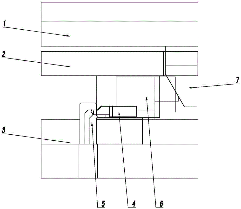
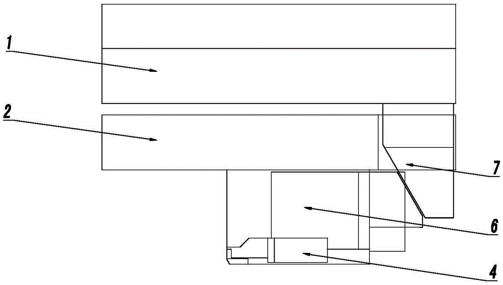
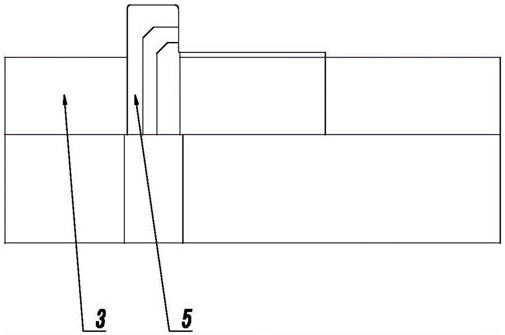
[0019] Such as Figure 4~7 Shown, the present invention mainly comprises punch fixed plate 1, unloading plate 2, concave die plate 3, side cutting punch 4, side cutting die 5, first side push plate 6 and second side push plate 7, punch fixed plate 1 and the concave template 3 are arranged facing up and down, and the lower end of the punch fixed plate 1 is connected to the second side push plate 7. The lower end of the punch fixing plate 1 is provided with a discharge plate 2, and the lower end of the discharge plate 2 is provided with a guide rail 8, and the first side push plate 6 is slidably connected in the guide rail 8.

[0020] The first side push plate 6 and the second side push plate 7 are connected by sliding fit on an inclined surface. During processing, the punch fixing plate 1 drives the second side push plate 7 to move down, and the secon...


PUM


Abstract

The invention relates to a punching mold, in particular relates to a side edge punching mold and belongs to the technical field of punching molds. The side edge punching mold comprises a male mold fixing plate, an unloading plate, a female mold plate, a side cutting male mold, a side cutting female mold, a first side pushing plate and a second side pushing plate, wherein the lower end of the male mold fixing plate is connected with the second side pushing plate; the lower end of the male mold fixing plate is provided with the unloading plate; the lower end of the unloading plate is provided with a guide rail; the first side pushing plate is connected in the guide rail in a sliding manner; the first side pushing and the second side pushing plate are in sliding fit connection by an inclined surface; the lower end of the side pushing plate is connected with the side cutting male mold by a bolt; the side surface of the unloading plate is connected with the side cutting female mold by a bolt. According to the side edge punching mold, under a condition of continuous working, phenomena of side cutting male mold nicking and tipping are avoided, punching gaps and the service life of the side cutting male and female molds are well ensured, the stability of product sizes is ensured, and the side edge punching mold is suitable for being used in large-scale batch production.

Description

technical field [0001] The invention relates to a blanking die, in particular to a side blanking die, which belongs to the technical field of blanking dies. Background technique [0002] With the continuous progress of the society and the continuous development of productivity, customers have put forward more stringent requirements for the current stamping products, and the precision of the products and the complexity of the molding process are getting higher and higher. Obviously, the common single upper and lower die blanking can no longer meet the current requirements. If the side blanking is used instead, this problem will be greatly improved. This structure will maximize the quality of the product, and at the same time, the processing accuracy of the product and the service life of the parts have also been greatly improved. [0003] In the existing technology, such as Figure 1~3 As shown, the side cutting die of the side blanking die is generally fixed on the die plat...

Claims


Application Information

Patent Timeline
Patent Type & Authority Applications(China)
IPC IPC(8): B21D28/14
Inventor 谈渊智王彦君
Owner WUXI MICRO RES PRECISION PRESS PARTS
Learn More