Implementation method of conducting dry-wet cycle by simulating soil body bearing load in engineering

A dry-wet cycle and realization method technology, applied in the direction of soil material testing, weighing by removing certain components, material inspection products, etc., can solve the problems of affecting the experimental results, large difference, slow dry-wet cycle process, etc., to achieve The effect of simple and cheap installation, convenient engineering application and easy operation

Active Publication Date: 2015-12-30
GUILIN UNIVERSITY OF TECHNOLOGY
View PDF6 Cites 6 Cited by
  • Summary
  • Abstract
  • Description
  • Claims
  • Application Information

AI Technical Summary

Problems solved by technology

However, the soil force simulated by the current experimental method is quite different from the actual engineering, and there are mainly the following limitations: (1) The dry-wet cycle process of the sample is carried out on a direct shear instrument, and the moisture content is determined by the The sample measurement cannot accurately control the moisture content of the sample in real time; the sample is tightly wrapped, and the dry-wet cycle process is slow; (2) the sample is subjected to the dry-wet cycle process in an unconstrained state, first make a larger sample, and the dry-wet cycle After the completion, the ring knife sample is made, which will cause multiple disturbances to the sample and affect the experimental results

Method used


Image

  • Implementation method of conducting dry-wet cycle by simulating soil body bearing load in engineering
  • Implementation method of conducting dry-wet cycle by simulating soil body bearing load in engineering
  • Implementation method of conducting dry-wet cycle by simulating soil body bearing load in engineering

Examples


Embodiment

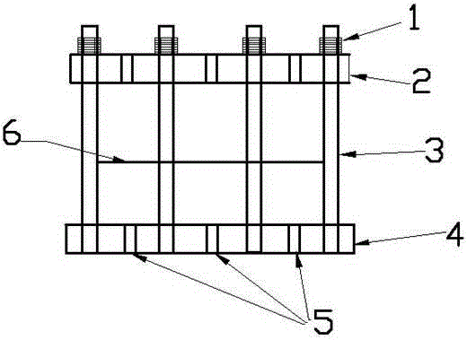
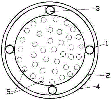
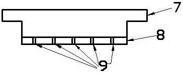
[0023] (1) Set up a device that simulates the dry-wet cycle of the soil under load in the project, including nut 1, fixed ring 2, vertical rod 3, lower bottom plate 4, lower bottom plate drainage hole 5, ring knife 6, cross Ridge 7, upper cover plate 8 and upper cover plate drainage hole 9, the full length of vertical rod 3 is threaded and is fixedly connected with lower base plate 4; cm; the internal diameter of the fixed ring 2 is slightly larger than the outer diameter of the ring knife 6, which is convenient for the ring knife 6 to be put in, and four vertical grooves are arranged at the diagonal positions on the ring wall of the fixed ring 2, and the internal thread of the vertical groove and the thread of the vertical rod 3 are interlocked, and the nut 1. The internal thread and the thread of the vertical rod 3 interlock; the whole device is made of PEEK plastic.

[0024] (2) make the ring knife sample 12 of required water content according to the experimental plan, resp...


PUM


Abstract

The invention discloses an implementation method of conducting a dry-wet cycle by simulating a soil body bearing load in engineering. A device is arranged for conducting the dry-wet cycle by simulating the soil body bearing load in engineering, wherein the device comprises nuts, a fixing ring, vertical rods, a lower bottom plate, lower bottom plate drainage holes, a cutting ring, a criss cross arris, an upper cover plate and upper cover plate drainage holes, a thread adheres to each vertical rod in the whole length, and the vertical rods are fixedly connected with the lower bottom plate; the upper end of the criss cross arris on the upper cover plate is one centimeter larger than the outer diameter of the fixing ring; the inner diameter of the fixing ring is slightly larger than the outer diameter of the cutting ring, so that the cutting ring is convenient to place therein, four vertical grooves are formed in diagonal positions of the ring wall of the fixing ring, an inner thread of each vertical groove is occluded with the thread of the corresponding vertical rod, and an inner thread of each nut is occluded with the thread of the corresponding vertical rod. By means of the device, the purpose of conducting soil body dry-wet cycle tests under the condition that the moisture content is controlled accurately is achieved. The device is simple and cheap in material, easy and convenient to operate and easy to grasp, the stress condition simulation is close to the engineering practice, and engineering application is facilitated.

Description

technical field [0001] The invention belongs to the technical field of geotechnical engineering test and engineering application, and particularly relates to a method for realizing dry-wet cycle under the condition that the soil bears load in the simulated engineering. Background technique [0002] The dry-wet cycle has a significant impact on the strength, modulus and other properties of the soil, and the dry-wet cycle of the soil is also one of the widely concerned issues in geotechnical engineering. At present, the research on the dry-wet cycle process of soil is mainly carried out through large-volume model experiments and laboratory small-volume sample experiments. However, the soil force simulated by the current experimental method is quite different from the actual engineering, and there are mainly the following limitations: (1) The dry-wet cycle process of the sample is carried out on a direct shear instrument, and the moisture content is determined by the The sampl...

Claims


Application Information

Patent Timeline
Patent Type & Authority Applications(China)
IPC IPC(8): G01N33/24G01N5/04G01N5/02
Inventor 吕海波董均贵徐云山季春生蒋熠成果灯常红帅刘丽王宗王勇
Owner GUILIN UNIVERSITY OF TECHNOLOGY
Why Eureka
Try Eureka