Photoelectric electric field near field scanner

A near-field scanning device, photoelectric technology, applied in the direction of electromagnetic field characteristics, etc., can solve the problems of complicated observation records and data analysis, inflexible control methods, and low measurement accuracy, so as to achieve vivid and variable resolution of three-dimensional field strength data The effect of shortening the rate and flexible and convenient scanning

Active Publication Date: 2018-03-16
HEBEI UNIV OF TECH
View PDF15 Cites 0 Cited by
  • Summary
  • Abstract
  • Description
  • Claims
  • Application Information

AI Technical Summary

Problems solved by technology

[0004] The technical problem to be solved by the present invention is to provide a photoelectric electric field near-field scanner, which is a three-dimensional photoelectric electric field near-field scanning device equipped with upper and lower two optical fiber crystal probes, which overcomes the electric field detection system itself in the prior art The introduction of space electromagnetic interference, complex observation records and data analysis, vibration generated during the movement, inflexible control methods and low measurement accuracy

Method used


Image

  • Photoelectric electric field near field scanner
  • Photoelectric electric field near field scanner
  • Photoelectric electric field near field scanner

Examples


Embodiment

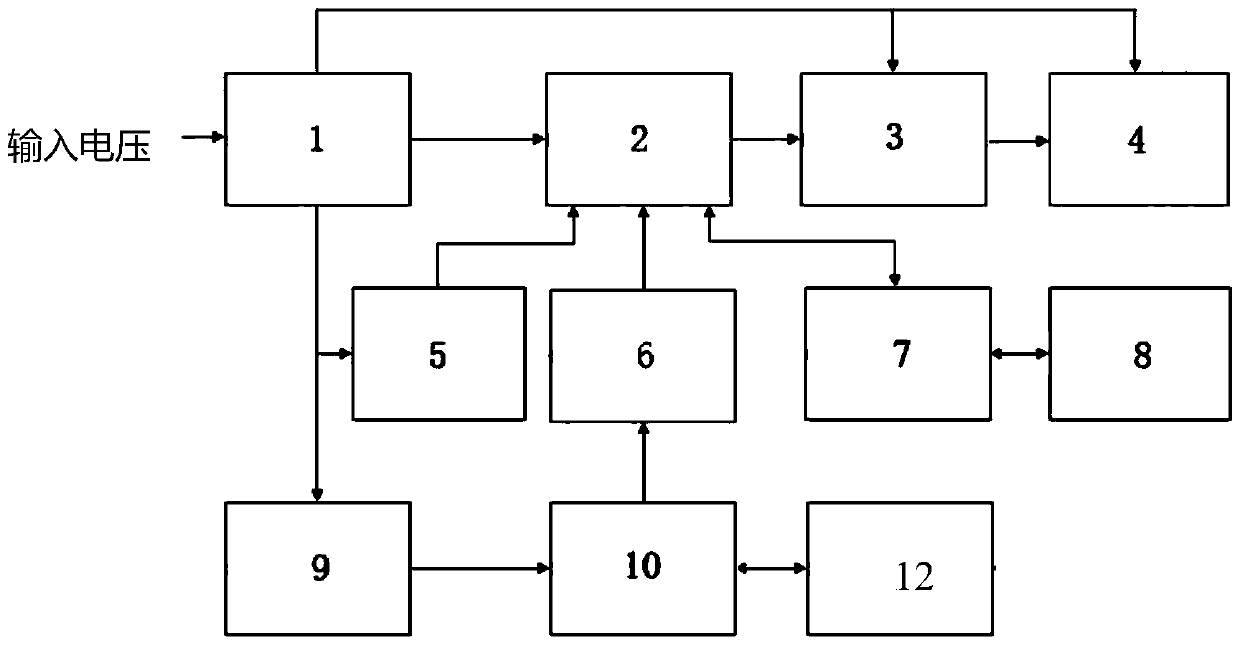
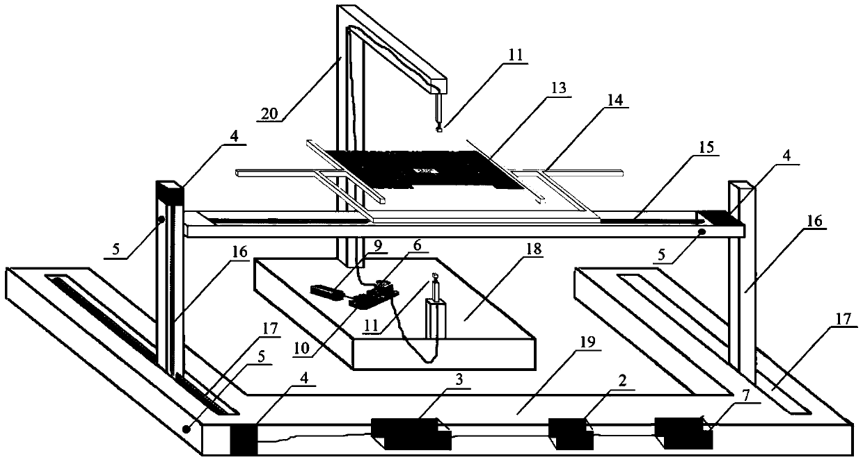
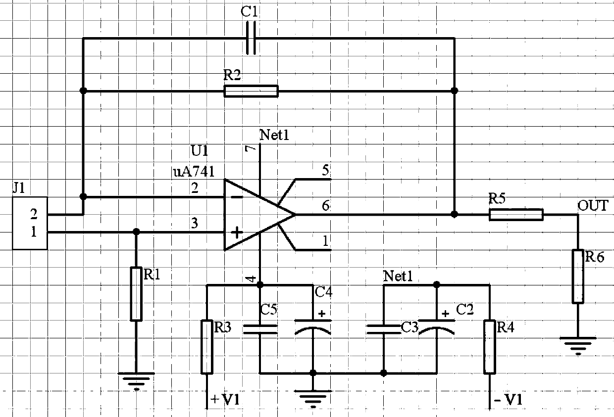
[0035] The photoelectric electric field near-field scanner of this embodiment according to figure 1 , figure 2 and image 3 The assembly structure of the shown embodiment includes an electric field near-field scanning device 12, a power supply 1, a controller 2, a drive module 3, three stepper motors 4, a three-way position sensor 5, a signal processing circuit 6, and a 485 bus communication module 7, Host computer 8, semiconductor laser 9 and optical circuit 10; the input voltage of power supply 1 is AC 220 volts, and the output of power supply 1 is provided with three circuits of DC 24V3A, DC positive 5V2A and DC negative 5V2A, among which power supply 1 outputs DC 24V3A to the drive module 3 and three stepper motors 4 supply power, power supply 1 outputs DC positive 5V2A and DC negative 5V2A to supply power to op amp uA741, power supply 1 outputs 5V2A to supply power to controller 2, three-way position sensor 5, semiconductor laser 9 and signal processing circuit 6 , thr...

Embodiment 2

[0046] In the photoelectric electric field near-field scanner of the present embodiment, except that the distance between the two optical fiber crystal probes 11 is 1 cm up and down, the adjustable range of the upper and lower probe adjustment arms 20 with a ruler is 1 cm, and the fixed frame of the circuit board to be tested is 1 cm. 14 can fix the circuit board 13 to be tested with a width of 1 cm, and the rail movement range of the X-axis guide rail 15, the Y-axis guide rail 16 and the Z-axis guide rail 17 is 1 cm, and the others are the same as in Embodiment 1.

Embodiment 3

[0048] In the photoelectric electric field near-field scanner of the present embodiment, except that the distance between the two optical fiber crystal probes 11 is 50cm up and down, the adjustable range of the upper and lower probe adjustment arms 20 with a scale is 50cm, and the fixed frame of the circuit board to be tested is 50cm. 14 can fix the circuit board 13 to be tested with a width of 50cm, and the rail movement range of the X-axis guide rail 15, the Y-axis guide rail 16 and the Z-axis guide rail 17 is 60cm, and the others are the same as in Embodiment 1.


PUM


Abstract

The photoelectric electric field near-field scanner of the present invention relates to a system for measuring magnetic variables and electric variables. , controller, drive module, three stepper motors, three-way position sensors, signal processing circuit, 485 bus communication module, upper computer, semiconductor laser and optical circuit; the scanner can scan both sides of the circuit board to be tested at the same time The near-field field strength of the electric field, no secondary interference and no radiation scanning of the parts to be tested, overcomes the introduction of space electromagnetic interference, complicated observation records and data analysis, and vibration generated during the moving process by the electric field detection system itself in the prior art , The control method is not flexible enough and the measurement accuracy is not high.

Description

technical field [0001] The technical proposal of the invention relates to a system for measuring magnetic variables and electric variables, specifically a photoelectric electric field near-field scanner. Background technique [0002] The electromagnetic compatibility of the circuit board is a link that cannot be ignored after the development of electronic technology to the high-speed era. The various electromagnetic radiation generated by the circuit board in operation will have a certain degree of influence on the surrounding electronic components and circuits. In the selection of components and the circuit board In the design process, electromagnetic compatibility design is a very important step, and the test and evaluation of electromagnetic radiation of circuit boards requires professional electromagnetic field strength testing equipment to complete. At present, the relatively mature technology in the world is to use probes made of micro-antennas or detection boards comp...

Claims


Application Information

Patent Timeline
Patent Type & Authority Patents(China)
IPC IPC(8): G01R29/08
Inventor 李尔平宋涛王蒙军
Owner HEBEI UNIV OF TECH
Why Eureka
Try Eureka