Multifunctional transformer mounting rack

A transformer and mounting frame technology, applied in the field of medical equipment, can solve problems such as time-consuming adjustments, unstable installation, and affecting the reliability and safety of transformers, and achieve the effect of simple structure, not easy to shake, and convenient iron core disassembly

Active Publication Date: 2015-12-30
SHANDONG HUACHI TRANSFORMER
View PDF7 Cites 6 Cited by
  • Summary
  • Abstract
  • Description
  • Claims
  • Application Information

AI Technical Summary

Problems solved by technology

[0003] Most of the existing transformer mounting frames are planar frames, and the two ends of the steel frame are provided with hoops connected with the poles. It takes a lot of time to adjust the center of gravity of the transformer to be located in t

Method used


Image

  • Multifunctional transformer mounting rack
  • Multifunctional transformer mounting rack
  • Multifunctional transformer mounting rack

Examples


Embodiment Construction

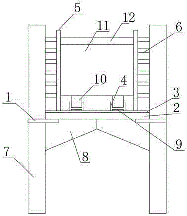
[0020] The invention provides a multifunctional transformer mounting frame, which is simple in structure and easy to use. By designing the bracket body as a U shape and setting a fixing groove at the lower end of the bottom wall, the transformer can be fixed and installed conveniently. The iron core passes through the hole to facilitate the disassembly of the iron core, the installation is stable, and it is not easy to shake.

[0021] In order to better understand the above-mentioned technical solution, the above-mentioned technical solution will be described in detail below in conjunction with the accompanying drawings and specific implementation methods.

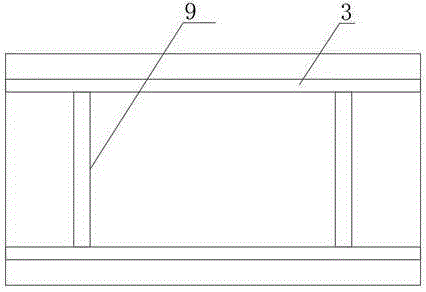
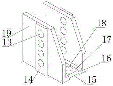
[0022] Such as Figure 1-Figure 3 As shown, a multifunctional transformer mounting frame includes a hoop plate 1, a support plate 2, a horizontal limit bar 3, a longitudinal limit bar 9, a support base 4, a vertical limit bar 5 and a push rod 6. One end of the above-mentioned hoop plate 1 is fixed on the utility pole 7, a...


PUM


Abstract

The invention provides a multifunctional transformer mounting rack. The multifunctional transformer mounting rack comprises hoop plates, a support plate, horizontal limit bars, longitudinal limit bars, support bases, vertical limit bars and propping rods, wherein one end of each hoop plate is fixed on a utility pole, the support plate is arranged on the upper sides of extending ends of the hoop plates, the horizontal limit bars and the longitudinal limit bars are arranged on the surface of the support plate, the upper surfaces of the support bases are matched with a base of a transformer, each support base comprises two side walls and one bottom wall, a concave part is arranged at the bottom of the bottom wall and matched with the width of each longitudinal limit bar, the vertical limit bars are arranged on two sides of the support plate, the multiple uniformly distributed propping rods are arranged on the surface of each vertical limit bar, and tail ends of the propping rods are propped against the corresponding utility pole. The multifunctional transformer mounting rack is simple in structure and convenient to use, the rack body is designed in a U shape, fixing grooves are formed in lower ends of the bottom walls, so that a transformer is fixed and mounted conveniently, with adoption of opposite iron core through holes formed in the vertical walls, iron cores are conveniently dismounted, mounting is stable, and low probability of shaking is realized.

Description

technical field [0001] The invention relates to the technical field of medical instruments, in particular to a multifunctional transformer mounting frame. Background technique [0002] The transformer is one of the core equipment of the power grid. On both sides of the road in the town, the transformer is often installed on a double-pole transformer mounting frame. The double-pole transformer mounting frame is stronger than the single-pole transformer mounting frame, and is suitable for 40-200kV.A transformers. The double-pole transformer mounting frame is H-shaped, and the transformer is installed between two vertical poles. The structure of the transformer mounting frame itself has a major impact on the firm installation of the transformer, which is related to the long-term stable operation of the transformer. [0003] Most of the existing transformer mounting frames are planar frames, and the two ends of the steel frame are provided with hoops connected with the poles. ...

Claims


Application Information

Patent Timeline
IPC IPC(8): H01F27/06H02B5/02
Inventor 陈同会曹中占胡良清
Owner SHANDONG HUACHI TRANSFORMER
Why Eureka
Try Eureka