Anti-falling device for antenna holding pole

A technology for holding poles and antennas, which is applied in the field of anti-fall devices for antenna holding poles, and can solve problems such as the falling of antenna holding pole bolts

Inactive Publication Date: 2015-12-30
SHANDONG LUNENG TAISHAN TOWER
View PDF0 Cites 0 Cited by
  • Summary
  • Abstract
  • Description
  • Claims
  • Application Information

AI Technical Summary

Problems solved by technology

[0003] The object of the present invention is to provide an anti-falling device for the antenna holding pole on the communication tower to solve the problem of the antenna holding pole falling after the bolt is loose

Method used


Image

  • Anti-falling device for antenna holding pole
  • Anti-falling device for antenna holding pole

Examples


Embodiment Construction

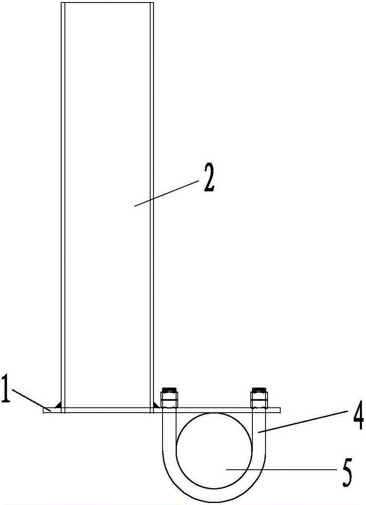
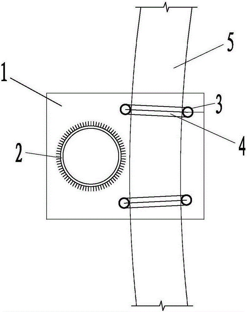
[0010] like figure 1 , 2 As shown, one side of the fixed plate 1 of the present invention is welded to one end of the antenna pole 2 , and two U-shaped bolts 4 are provided on the other side of the fixed plate 1 through the mounting holes 3 . Through the above settings, the antenna is inserted into the antenna pole 2 of the present invention, and the antenna pole 2 is fixed on the support member 5 of the communication tower through two U-shaped bolts 4 . During use, the antenna pole 2 will not vibrate due to the influence of wind force, and the bolts fixing the antenna pole 2 will not loosen. On the support member 5, the antenna pole 2 will not fall. The invention can flexibly adjust the fixed position, enhance the stability of the structure, solve the problem of anti-falling and improve the safety performance.


PUM


Abstract

The invention discloses an anti-falling device for an antenna holding pole. The anti-falling device is characterized in that one side of a fixing plate is connected with the end face of one end of the antenna holding pole in a welded mode, and the other side of the fixing plate is provided with two U-shaped bolts through installation holes. By means of the arrangement, the antenna holding pole is fixed to a supporting part of a communication tower through the two U-shaped bolts, the fixing position can be adjusted flexibly, the stability of the structure is enhanced, the anti-falling purpose is achieved, and safety performance is improved.

Description

technical field [0001] The invention relates to the field of communication equipment, in particular to an antenna pole-holding anti-falling device used on communication towers. Background technique [0002] The current antenna holding poles for communication towers are conventionally fixed by U-shaped bolts directly on the platform support. During long-term use, due to the outdoor use, the fastening bolts will become loose due to the vibration of the wind-forced antenna, causing The antenna pole fell, affecting the normal use of the antenna and posing safety hazards. Contents of the invention [0003] The object of the present invention is to provide an antenna pole-holding anti-drop device used on a communication tower to solve the problem of antenna pole-holding bolts falling after loosening. [0004] In order to achieve the above object, one side of the fixing plate of the present invention is welded to one end surface of the antenna pole, and two U-shaped bolts are pr...

Claims


Application Information

Patent Timeline
Patent Type & Authority Applications(China)
IPC IPC(8): H01Q1/12
Inventor 刘洋徐贞东赵小龙孙巍
Owner SHANDONG LUNENG TAISHAN TOWER
Why Eureka
Try Eureka