Anti-slip fixing tray

A technology for fixing trays and trays, used in conveyor objects, printing, rotary printing machines, etc., can solve the problems of high scratch ratio, easy occurrence of silicone printing, damage, etc., to avoid sliding damage, reduce scratch ratio, application high value effect

Inactive Publication Date: 2019-11-15
HUNAN SOKAN NEW MATERIAL
View PDF10 Cites 0 Cited by
  • Summary
  • Abstract
  • Description
  • Claims
  • Application Information

AI Technical Summary

Problems solved by technology

[0002] In the production process, the glass cover plate for mobile phone or tablet usually needs to go through multiple processes such as incoming material-loading printing-unloading-discharging-transportation-baking-transportation-loading printing-unloading-discharging-transportation-baking , it is easy to be damaged due to the sliding of the glass cover in the tray, especially for the large glass cover over 10 inches, the scratch rate is very high, which affects the product yield
[0003] To overcome this defect, a common method is to place a silicone pad in the tray, which can reduce the sliding of the glass sheet to a certain extent, but it is prone to silicone prints during high-temperature baking.
Another method is to place a Teflon net in the tray. This method cannot effectively prevent the glass from sliding, and it is easy to cause friction and scratches due to the overlapping of glass sheets.

Method used


Image

  • Anti-slip fixing tray
  • Anti-slip fixing tray
  • Anti-slip fixing tray

Examples


Embodiment Construction

[0025] In order to make the purpose, technical solutions and advantages of the embodiments of the present invention more clear, the following will be clearly and completely described in conjunction with the accompanying drawings. Apparently, the described embodiments are part of the embodiments of the present invention, not all of them.

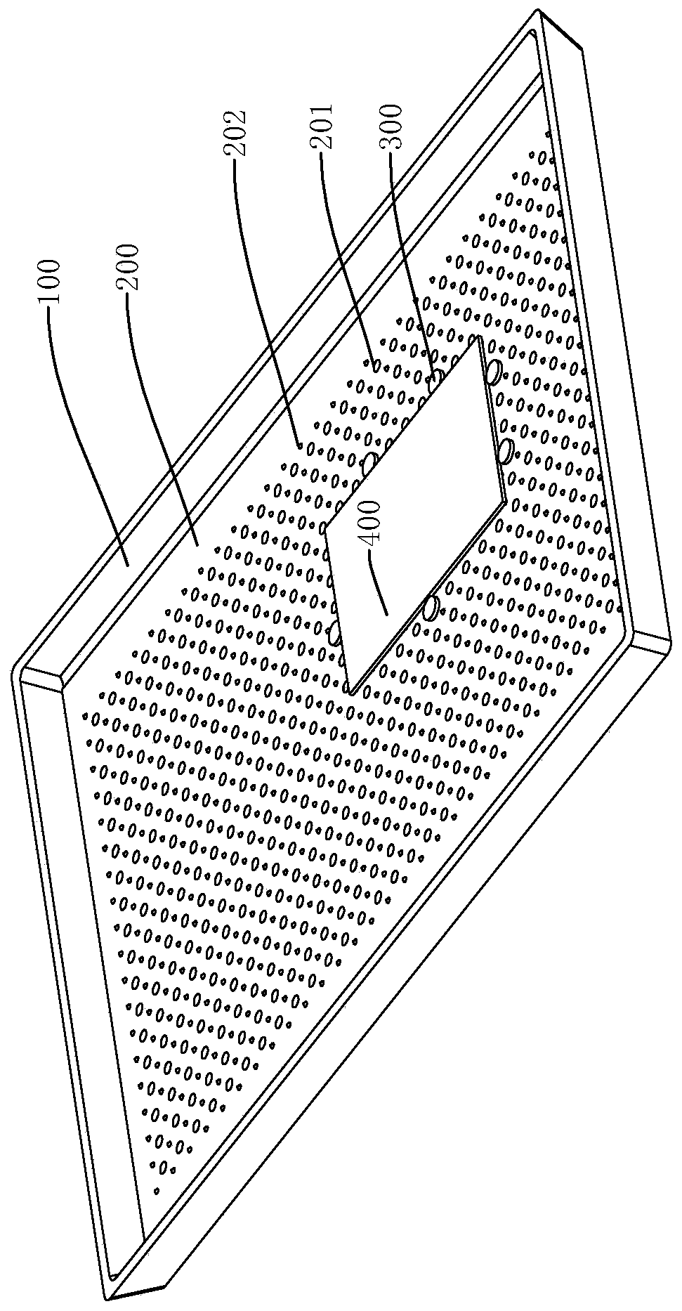
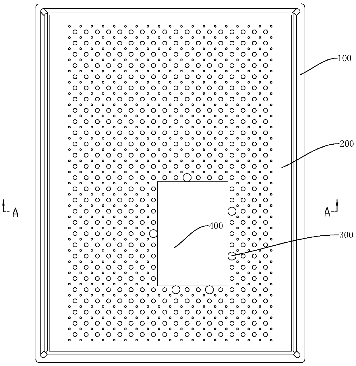
[0026] like Figure 1-3 and Figure 5 The shown non-slip fixed tray includes: a tray body 100 , a release pad 200 and several rubber nails 300 .

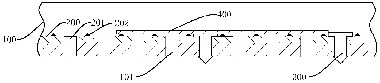
[0027] The tray body 100 is provided with a plurality of first through holes 101 , the release pad 200 is laid on the tray body 100 , and the release pad 200 is provided with a plurality of second through holes 201 corresponding to the first through holes 101 one by one.

[0028] The structure of rubber nail 300 is as follows Figure 4 As shown, it includes a positioning cap 301, a clamping post 302 and a plug head 303 arranged in sequence from top to bottom, and the plug head end of the rubber n...


PUM


Abstract

The invention discloses an anti-slip fixing tray. The tray comprises a tray body, a release pad and a plurality of rubber nails; the tray body is provided with a plurality of first through holes; therelease pad is provided with a plurality of second through holes in one-to-one correspondence with the first through holes; and the rubber nails comprise positioning caps, clamping columns and plug heads which are sequentially arranged from top to bottom, wherein the plug head ends of the rubber nails can sequentially penetrate through the second through holes and the first through holes to be clamped on the tray body, and the positioning caps protrude out of the upper surface of the release pad. According to the anti-slip fixing tray, the plurality of rubber nails are clamped at different positions of the tray body correspondingly, an enclosed area formed by the rubber nails can be utilized to accommodate and fix a glass cover plate, thus preventing the situation that the glass cover plate is damaged due to sliding in a baking or transportation process; and meanwhile, the rubber nails can be arranged at the different positions of the tray body according to the size of the glass coverplate. Therefore, according to the scheme, the scratch proportion of the glass cover plate can be greatly reduced, so that the anti-slip fixing tray has remarkable application values.

Description

technical field [0001] The invention relates to a pallet, in particular to a non-slip fixed pallet. Background technique [0002] In the production process, the glass cover plate for mobile phone or tablet usually needs to go through multiple processes such as incoming material-loading printing-unloading-discharging-transportation-baking-transportation-loading printing-unloading-discharging-transportation-baking , it is easy to be damaged due to the sliding of the glass cover in the tray, especially for the large glass cover over 10 inches, the scratch rate is very high, which affects the product yield. [0003] To overcome this defect, a common method is to place a silicone pad in the tray. This method can reduce the sliding of the glass sheet to a certain extent, but it is prone to silicone marks during high-temperature baking. Another method is to place a Teflon net in the tray. This method cannot effectively prevent the glass from sliding, and it is easy to cause fricti...

Claims


Application Information

Patent Timeline
Patent Type & Authority Applications(China)
IPC IPC(8): B41F19/00B41F23/04B65G47/74B65G47/22
CPCB41F19/00B41F23/04B65G47/22B65G47/74B65G2201/0214
Inventor 刘建富李玉良王卫国缪培凯吕国强杨波凌云剑伍松符饶生
Owner HUNAN SOKAN NEW MATERIAL
Why Eureka
Try Eureka