Locking device

A technology for locking devices and locking positions, applied in transportation and packaging, web wheels, connecting components, etc., can solve problems such as time-consuming, achieve high-speed connection process, time-limited or permanent connection, and shorten the time

Active Publication Date: 2015-12-30
贝恩德·斯托克
View PDF7 Cites 7 Cited by
  • Summary
  • Abstract
  • Description
  • Claims
  • Application Information

AI Technical Summary

Problems solved by technology

[0003] The locking device described above has the disadvantage that the connection between the parts takes time if three to five or more screws or nuts need to be unscrewed and reassembled correctly
In addition, there is the disadvantage that in order to connect screws or nuts tools such as torque wrenches are required, which are not always readily available
[0005] However, this quick closure has the disadvantage that, when the actuating mechanism is actuated, said actuating mechanism does not switch automatically into the locked position

Method used


Image

  • Locking device
  • Locking device
  • Locking device

Examples


Embodiment Construction

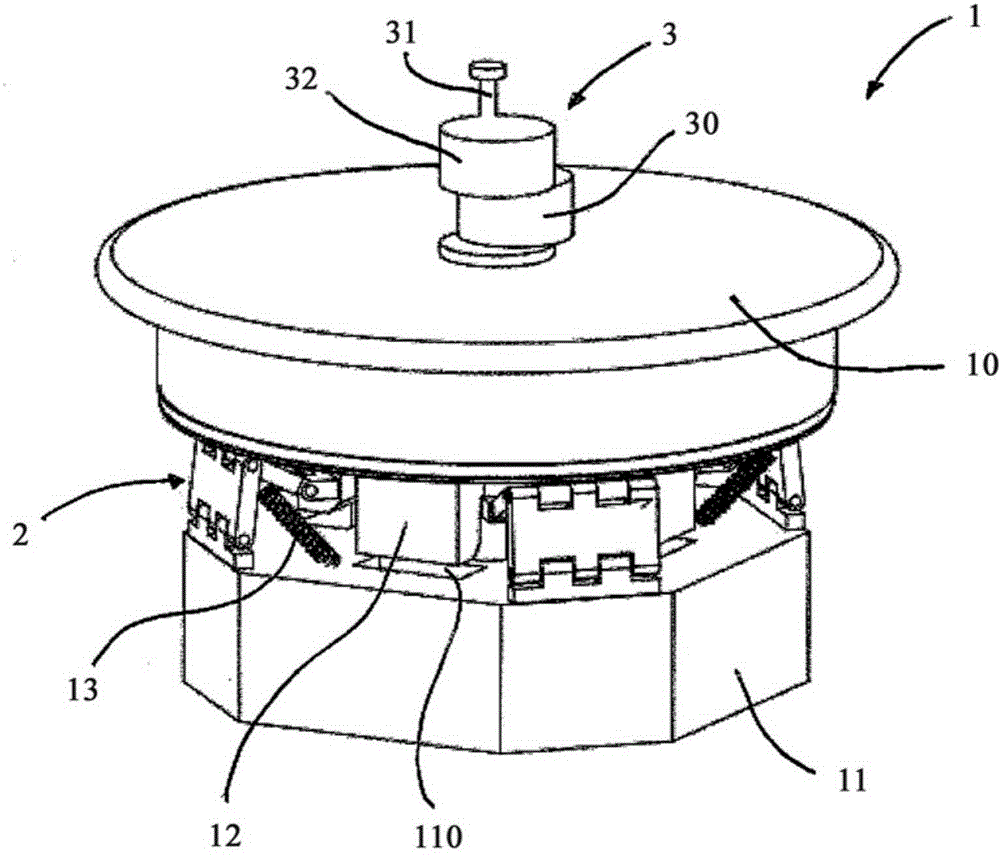
[0066] figure 1 The locking device 1 shown has an actuating mechanism 10 which, in particular, is connected directly to the fixing device 3 . The fixing device 3 has a fixing screw 31 , a cylindrical extension 32 and an eccentric cylindrical disk 30 . Here, the cylindrical extension 32 supports the fixing bolt 31 . In particular, the cylindrical extension 32 has a groove into which the fixing bolt 31 can be releasably guided. The diameter of the cylindrical disk 30 may correspond to the diameter of the cylindrical extension 32 .

[0067] On the side of the actuating mechanism 10 opposite to the fixing device 3, the actuating mechanism is via one, or such as figure 1 Mechanical displacement means in the form of four folding means 2 shown by way of example are connected to the base body 11 . The actuating mechanism 10 is movable relative to the base body 11 . The displacement device 2 is coupled to the base body 11 via a tensioning device 13 in the form of a spring. The te...


PUM


Abstract

The invention relates to a locking device having a main part, a locking means for locking the main part to a mating part, an actuating means that can move relative to the main part and can be brought into contact with the locking means, and at least one displacement device. When the actuating means is actuated the displacement device moves the actuating means automatically into a locking position. In the locking position the actuating means is in contact with the locking means and moves it into a locked state.

Description

technical field [0001] The invention relates to a locking device. Background technique [0002] The use of locking devices to connect at least two components is known from numerous technical fields of the prior art. For example, it is known to fasten the rim and thus the wheel to the axle by means of a number of threaded connections. The threaded connectors are arranged on the axle in a circular arrangement around the central axis. In the case of sports cars, it is known to carry out the connection by means of a single central nut or central screw. In DE610025A and DE625310A alternative connection types are disclosed, in which the connection of the rim to the axle is achieved by clamping clamps. [0003] The aforementioned locking devices have the disadvantage that the connection between the parts takes time if three to five or more screws or nuts need to be unscrewed and reassembled correctly. Furthermore, there is the disadvantage that, in order to connect the screws o...

Claims


Application Information

Patent Timeline
Patent Type & Authority Applications(China)
IPC IPC(8): B60B3/14F16B21/16
CPCB60B3/14F16B21/165Y10T403/592F16B21/065
Inventor 贝恩德·斯托克
Owner 贝恩德·斯托克
Why Eureka
Try Eureka