Novel horizontal type multilevel vortex pump

A swirl pump, horizontal technology, applied in the field of horizontal multi-stage pumps, can solve the problems of frequent replacement, failure to meet the use requirements, rapid wear of pump seal rings, guide vane sleeves, etc., to ensure no axial series movement Effect

Inactive Publication Date: 2016-01-06
苏州邦普赛司流体工程有限公司
View PDF5 Cites 2 Cited by
  • Summary
  • Abstract
  • Description
  • Claims
  • Application Information

AI Technical Summary

Problems solved by technology

[0002] The existing horizontal multi-stage pump products mainly adopt centrifugal pump structure. The running gaps of the high and low pressure chambers in the pump, that is, the water inlet section, the middle section and the water outlet section, and the matching gap between them and the impeller are sealed with sealing rings; The impellers of multi-stage centrifugal pumps will add up to generate a large axial force. Therefore, it is necessary to set a balance plate to balance the axial force. It has the following disadvantages: to produce the same head, the diameter of the impeller of the centrifugal pump is about 20% larger than that of the swirl pump , resulting in an increase in the volume of the pump; in an environment with variable flow and constant pressure fluid delivery requirements, the head of the centrifugal pump changes with the flow rate, which will not meet the use requirements
After long-term operation, the pump seal ring and guide vane sleeve will wear quickly, resulting in a decline in pump performance; the balance plate and balance ring are a pair of high-speed rotating friction pairs, which wear out quickly during operation and need to be replaced frequently
Due to the axial series movement generated during the operation of the balance disc and the rotor will have a large axial displacement after rapid wear and tear, the shaft seal of this type of multi-stage centrifugal pump should not use a sealed structure, and only soft packing can be used. , resulting in large pump leakage and reduced efficiency

Method used


Image

  • Novel horizontal type multilevel vortex pump

Examples


Embodiment Construction

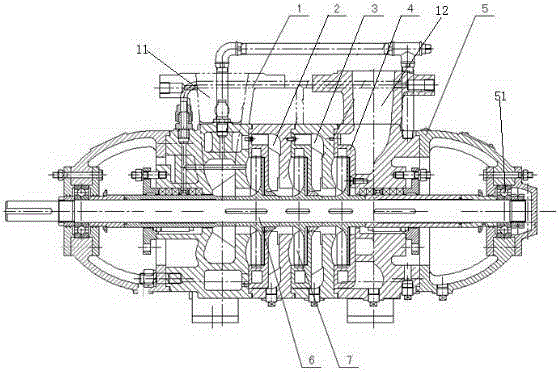
[0010] The present invention will be further described below in conjunction with accompanying drawing of description and embodiment:

[0011] As shown in the figure, the novel horizontal multistage swirl pump includes a pump body 1, a rotor part 6 connected with three sets of swirl pump impellers 7, and two bearing bodies 5, and the two bearing bodies 5 are respectively connected to two ends of the pump body. end, the rotor part is rotatably installed in the pump body and the two ends of the rotor part are respectively connected with the bearing body; the outer side of the pump body is respectively provided with a water inlet 11 and a water outlet 12, and the middle part of the pump body is provided with interconnected The water inlet section chamber 2, the middle section chamber 3 and the water outlet section chamber 4, three sets of swirl pump impellers are respectively located in the water inlet section chamber, the middle section chamber and the water outlet section chamber...


PUM


Abstract

The invention relates to a horizontal type multilevel vortex pump which comprises a pump body, a rotor part connected with three groups of vortex pump impellers, and two bearing bodies, wherein the two bearing bodies are connected onto two ends of the pump body respectively; the rotor part is rotatably arranged in the pump body in a penetrating manner; two ends of the rotor part are connected with the bearing bodies respectively; a water inlet and a water outlet are formed in the outer sides of the pump body respectively; a water inlet section chamber, a middle section chamber and a water outlet section chamber communicated with each other are sequentially arranged in the middle of the pump body; the three groups of vortex pump impellers are positioned in the water inlet section chamber, the middle section chamber and the water outlet section chamber respectively; the water inlet section chamber is communicated with the water inlet; the water outlet section chamber is communicated with the water outlet; the water inlet section chamber and the middle section chamber are vortex pump type chambers; the vortex pump impellers are provided with corresponding back blades. The horizontal type multilevel vortex pump is not provided with a sealing ring, so that the horizontal type multilevel vortex pump has no sealing operation interval and can avoid the problem that the performance of the pump is declined due to increased operation interval of the pump body and the impellers after abrasion.

Description

technical field [0001] The invention relates to a horizontal multistage pump, and proposes to manufacture the horizontal multistage swirl pump by using the principle of the swirl pump. Background technique [0002] The existing horizontal multi-stage pump products mainly adopt centrifugal pump structure. The running gaps of the high and low pressure chambers in the pump, that is, the water inlet section, the middle section and the water outlet section, and the matching gap between them and the impeller are sealed with sealing rings; The impellers of multi-stage centrifugal pumps will add up to generate a large axial force. Therefore, it is necessary to set a balance plate to balance the axial force. It has the following disadvantages: to produce the same head, the diameter of the impeller of the centrifugal pump is about 20% larger than that of the swirl pump , resulting in an increase in the volume of the pump; in an environment with variable flow and constant pressure flui...

Claims


Application Information

Patent Timeline
Patent Type & Authority Applications(China)
IPC IPC(8): F04D1/06F04D29/046F04D29/42
Inventor 王强刘强
Owner 苏州邦普赛司流体工程有限公司
Why Eureka
Try Eureka