Securing element

A technology for fixing parts and components, applied in the direction of threaded fasteners, connecting members, connectors specially modified for tensile loads, etc.

Inactive Publication Date: 2015-09-16
FISCHERWERKE ARTUR FISCHER GMBH & CO KG
View PDF10 Cites 1 Cited by
  • Summary
  • Abstract
  • Description
  • Claims
  • Application Information

AI Technical Summary

Problems solved by technology

A disadvantage of the known fastening element is that, during assembly of the fastening element, the nut must be tighten

Method used


Image

  • Securing element
  • Securing element

Examples


Embodiment Construction

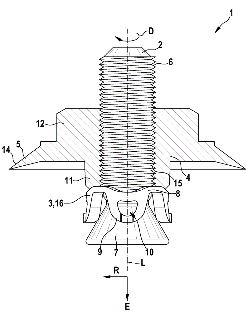
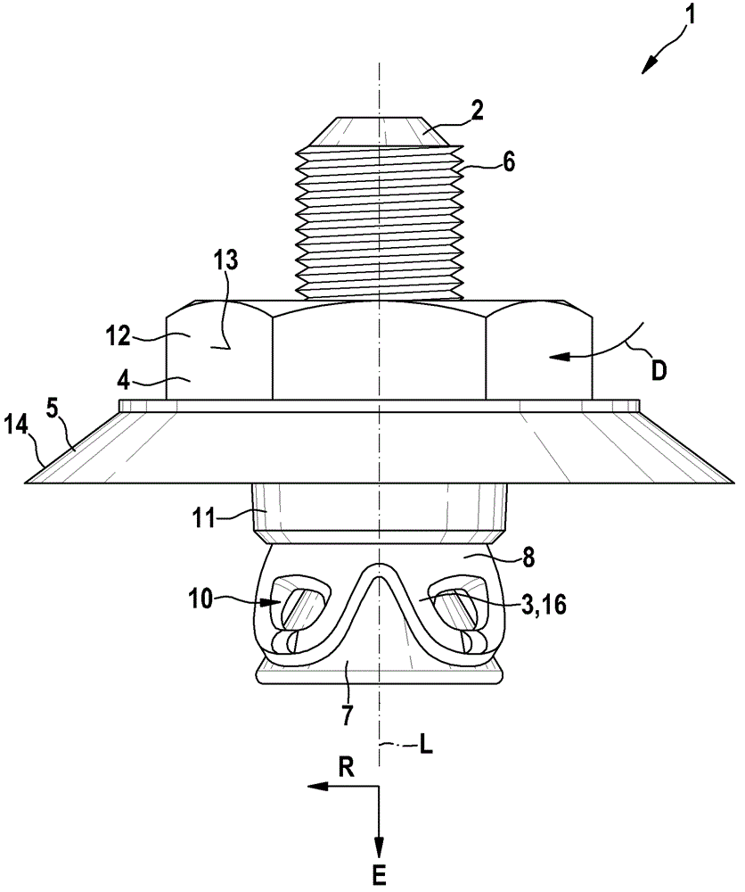
[0017] exist figure 1 and 2 A fastening element 1 according to the invention is shown in FIG. 1 for fastening components (not shown) on a fastening base (also not shown). The fixing part 1 consists of a shank 2, an expansion part 3 and a nut 4 on which a disc 5 is integrally formed.

[0018] The shank 2 is formed as a conical rod with a cylindrical section, which extends in the direction of the longitudinal axis L of the fastening part 1 and has an external thread 6 , to which an expansion body 7 adjoins forward in the insertion direction E. The expansion body 7 is shaped as a frusto-conical body, which increases in diameter in the direction of insertion E. The expansion part 3 is a sleeve 8 which forms a closed ring, on which a sheet-shaped expansion lug 9 is integrally arranged, the free end of which forms the front end of the expansion part 3 . The expansion lugs 9 are rounded at their front ends and each have an opening 10 which is arranged centrally in the surface of e...


PUM


Abstract

The invention relates to a securing element (1) for securing a component to a securing base, having a shank (2) which has an external thread (6) and an expansion body (7), an expansion element (3) which is arranged in an axially movable manner on the shank (2) and which can be expanded by moving axially on the shank (2) by means of the expansion body (7), and a nut (4) which has an internal thread (15) and which is arranged on the external thread (6) of the shank (2). The application of a torque enables the nut (4) to be rotated on the external thread (6) such that the expansion element (3) is moved against the expansion body (7) by means of the nut (4). According to the invention, in order to simplify the mounting of the securing element (1), the internal thread (15) is designed such that the external thread (6) is released after expansion of the expansion element (3) such that the nut (4) can rotatable substantially without axial movement on the shank (2).

Description

technical field [0001] The invention relates to a fastening element having the features of the preamble of claim 1 . Background technique [0002] A fastening element is known from laid-open document DE 40 30 498 A1, by means of which components can be fastened to a fastening base. Fastening elements are used in particular for fastening parts of the substructure to façade panels made of natural stone or ceramic. The fixing part is composed of a handle rod, an expansion ring as an expansion part, a plastic plate and a nut, and the handle rod has an external thread and an expansion body formed by an expansion cone. By turning the nut on the external thread of the shank, the plastic disk is pressed against the expansion ring and the expansion ring is pushed onto the expansion cone, whereby the expansion ring is expanded and the fixing part is fixed in the borehole in the fixed foundation . A disadvantage of the known fastening element is that, during assembly of the fastenin...

Claims


Application Information

Patent Timeline
IPC IPC(8): F16B13/08E04F13/08F16B31/02E06B3/54
CPCF16B13/0858F16B31/021F16B2013/007E04F13/0835E04F13/14
Inventor H.博内特A.考普
Owner FISCHERWERKE ARTUR FISCHER GMBH & CO KG
Why Eureka
Try Eureka