Gyroscope and balance ring thereof
A technology of balance ring and gyroscope, applied in the direction of rotating gyroscope, etc., can solve the problem that the counterweight is not easy to disassemble, and achieve the effect of improving debugging efficiency and easy disassembly
- Summary
- Abstract
- Description
- Claims
- Application Information
AI Technical Summary
Problems solved by technology
Method used
Image
Examples
Embodiment Construction
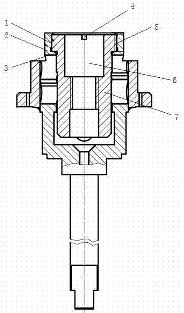
[0016] An example of a gyroscope figure 1 Shown: including the balance ring 2 and the counterweight 7, the balance ring is provided with a mounting hole 1 whose axis extends in the up and down direction, the wall of the mounting hole is provided with an internal thread, and the wall of the mounting hole is provided at the lower end of the internal thread There is an inversion edge 3. The counterweight is a sleeve-like structure, and the counterweight has an inner hole 6 coaxial with the installation hole (that is, a central hole). The outer peripheral surface of the counterweight is provided with an external thread 5 that cooperates with the inner thread. The outer peripheral surface of the counterweight An inner concave step is arranged on the lower end of the outer thread, and the step surface of the inner concave step is used to stop and cooperate with the upper end surface of the inner turning edge so as to prevent the counterweight from continuing to move downward. An adh...
PUM
 Abstract
Description
Claims
Application Information
 - R&D
- Intellectual Property
- Life Sciences
- Materials
- Tech Scout
- Unparalleled Data Quality
- Higher Quality Content
- 60% Fewer Hallucinations
Browse by: Latest US Patents, China's latest patents, Technical Efficacy Thesaurus, Application Domain, Technology Topic, Popular Technical Reports.
© 2025 PatSnap. All rights reserved.Legal|Privacy policy|Modern Slavery Act Transparency Statement|Sitemap|About US| Contact US: help@patsnap.com

