A brushless motor installation structure with a power control box

A power control box, brushless motor technology, applied in the direction of electromechanical devices, electrical components, electric components, etc., can solve the problem that the rotation and movement of the shock absorbing ring cannot be effectively solved, the difficulty and cost of maintenance and repair are increased, and the overall size of the equipment is increased. Large and other problems, to achieve the effect of compact structure, avoiding rotation and movement, and saving maintenance costs

Active Publication Date: 2018-10-02
CHANGZHOU XIANGMING ELECTROMOTOR
View PDF5 Cites 0 Cited by
  • Summary
  • Abstract
  • Description
  • Claims
  • Application Information

AI Technical Summary

Problems solved by technology

The installation of the motor body and the power control box mainly adopts the following two installation methods, 1. Separate installation: the motor body and the power control box are installed in different positions of the equipment, which will increase the overall size of the equipment and also require External lines, which not only increase the installation workload, but also increase the cost due to the increase in line length. 2. Integral installation: install the power control box on the motor bracket used to support the motor, which will cause some Different motor models (different sizes) interfere with the position of the power control box and the motor bracket, which increases the difficulty and cost of later maintenance and repair
Moreover, neither of the above two installation methods can effectively solve the problem of rotation and movement of the shock absorbing ring during transportation and use.

Method used


Image

  • A brushless motor installation structure with a power control box
  • A brushless motor installation structure with a power control box
  • A brushless motor installation structure with a power control box

Examples


Embodiment Construction

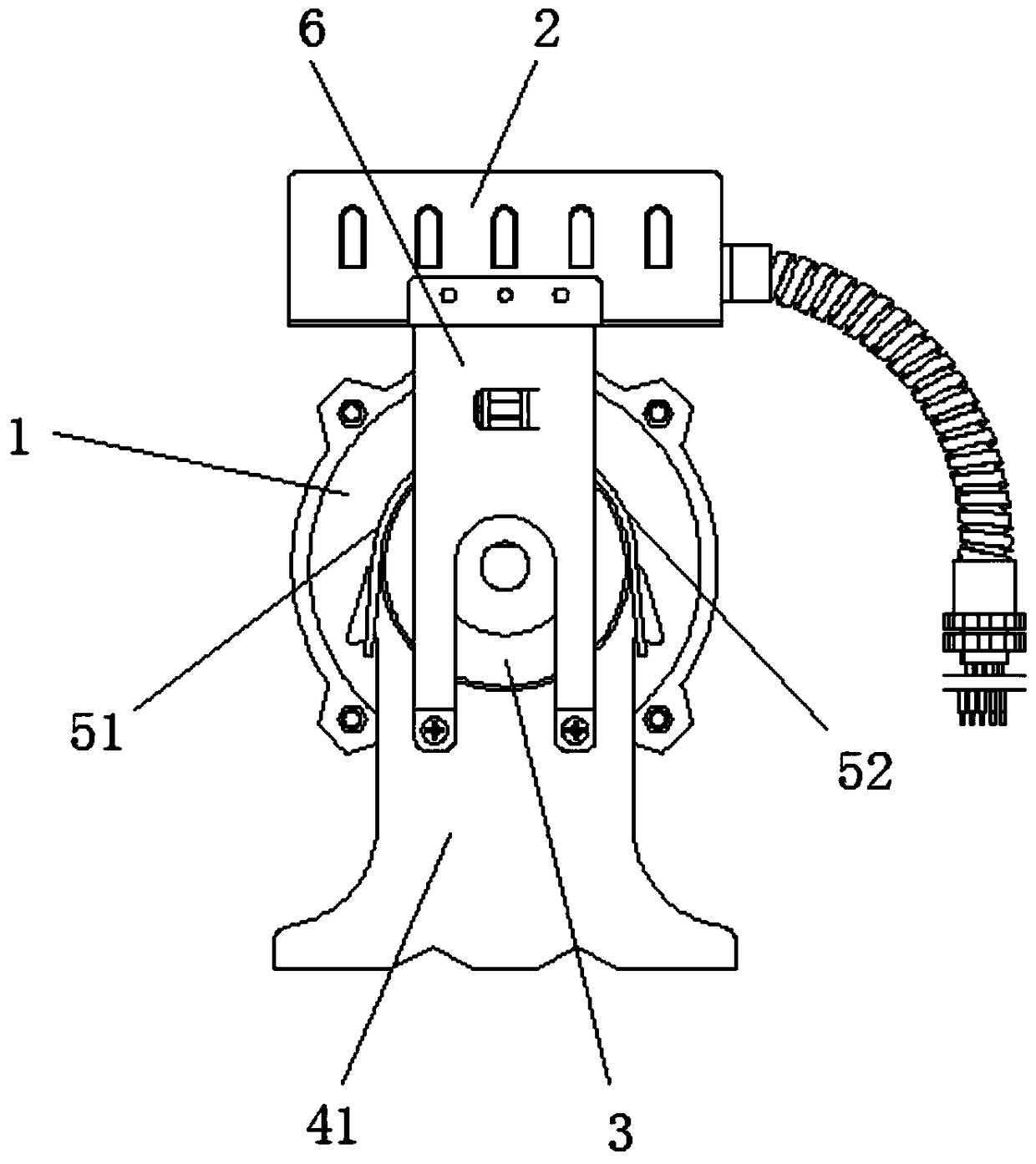
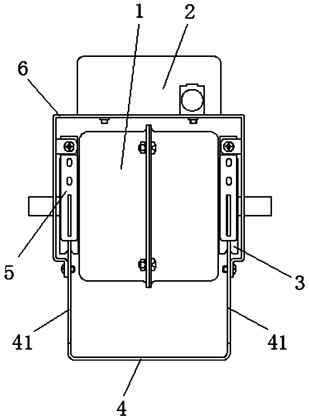
[0017] See Figure 1 to Figure 3 , the present invention includes a motor 1, a power control box 2, a shock absorbing ring 3, a base bracket 4 and a clamp assembly 5; the two ends of the base bracket protrude upward from support plates 41, and grooves are provided on each support plate 41 and a block; the clip assembly 5 includes a first clip 51, a second clip 52 and a connecting bolt; the lower ends of the first clip 51 and the second clip 52 are provided with buckles that match the block groove, the upper ends of the first clip 51 and the second clip 52 are provided with connecting holes; the two ends of the housing of the motor 1 are provided with shock absorbing rings 3, and the shock absorbing rings 3 are clamped on the support at the two ends of the base bracket 4. In the groove of the plate 41; the lower ends of the first buckle clip 51 and the second buckle clip 52 are buckled on the support plate 41 through the buckle groove and the block, and the first buckle clip 51...


PUM


Abstract

The invention relates to a brushless motor mounting structure with a power supply control box. The brushless motor mounting structure comprises a motor, the power supply control box, damping rings, a base support and a clamping assembly. Two ends of the base support extend upwards to form support plates. Two ends of a housing of the motor are respectively provided with the damping ring. The damping rings are clamped to the support plates on two ends of the base support through the clamping assembly. The brushless motor mounting structure simultaneously comprises a power supply control box support. The power supply control box support comprises a bearing plate. Two ends of the bearing plate are provided with connecting plates. The connecting plates on two ends of the bearing plate are fixedly connected with support plates on two ends of the base support. The power supply control box is fixedly connected to the bearing plate. According to the invention, the compact structures of the motor and the power supply control box are ensured, and the damping rings are effectively prevented from rotating and moving in a transportation or usage process.

Description

technical field [0001] The invention relates to a brushless motor installation structure with a power control box. Background technique [0002] With the continuous improvement of the country's requirements for energy saving, emission reduction and high efficiency of motors, the motors used in the traditional HVAC and air conditioning industries have gradually transformed from the original AC asynchronous motors to DC brushless motors with high efficiency and energy saving. [0003] The DC brushless motor currently used in the market includes a motor body and a power control box (including power AD / DC conversion, motor drive control). In the application of brushless DC motor engineering, these two parts need to be connected and fixed. The installation of the motor body and the power control box mainly adopts the following two installation methods, 1. Separate installation: the motor body and the power control box are installed in different positions of the equipment, which ...

Claims


Application Information

Patent Timeline
Patent Type & Authority Patents(China)
IPC IPC(8): H02K5/24H02K5/22
Inventor 张敏姚红伟林勇张韦明
Owner CHANGZHOU XIANGMING ELECTROMOTOR
Why Eureka
Try Eureka