Light-emitting diode (LED) lighting device and lighting method

A technology of LED lighting and lighting equipment, applied in the field of lighting and LED lighting, can solve the problems of inconvenience of life, loss of orientation perception and visual perception, damage to vision health, etc., and achieve the effect of convenient and quick use, high application and promotion value

Inactive Publication Date: 2016-01-06
陈海锋
View PDF4 Cites 4 Cited by
  • Summary
  • Abstract
  • Description
  • Claims
  • Application Information

AI Technical Summary

Problems solved by technology

[0002] LED lighting technology is widely used around the world due to its advantages of low energy consumption, low cost, high brightness, and long life. The drastic light changes during the operation of switching lights will not only cause eye discomfort and damage vision health, but also cause inconvenience to people's lives, and even lead to certain unsafe factors.
For example, after turning off the lights in a completely dark environment, the lighting equipment suddenly switches from the strong lighting state to the extinguished state, people will feel dizzy, and lose orientation perception and visual perception for a short time. At this time, when leaving the switch position It is easy to cause injuries such as collisions and falls
However, other existing ways to adjust the brightness of lighting equipment, such as the use of remote control circuits, potentiometers, gear switches and other adjustment methods, have disadvantages such as relatively complicated operation, inconvenient use, changes or additional wiring, configuration of remote controls, and high cost. And it does not have the function of automatically performing humanized lighting after the switch lamp operation described in the present invention

Method used


Image

  • Light-emitting diode (LED) lighting device and lighting method

Examples


Embodiment Construction

[0011] In order to facilitate understanding of the present invention, the present invention will be described in more detail below with reference to the accompanying drawings and specific embodiments. While exemplary embodiments of the present disclosure are shown in the drawings, it should be understood that the present disclosure may be embodied in various forms and should not be limited by the embodiments set forth herein. Rather, these examples are provided so that the present disclosure will be more thoroughly understood, and will fully convey the scope of the disclosure to those skilled in the art.

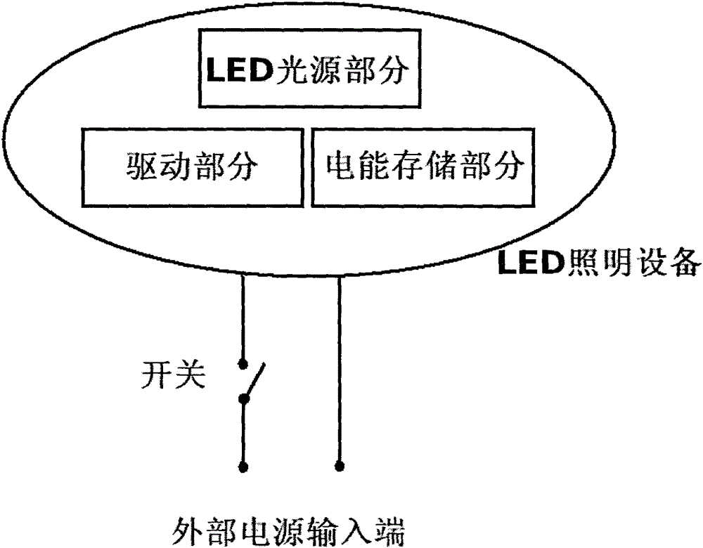
[0012] The accompanying drawings show a schematic diagram of an LED lighting device according to an embodiment of the present invention.

[0013] As shown in the drawings, the above-mentioned LED lighting device includes a driving part, an electric energy storage part and an LED light source part. Wherein, the driving part includes a duty cycle or input current control circ...


PUM


Abstract

The invention discloses a light-emitting diode (LED) lighting device, which comprises a drive part, an electric energy storage part and an LED light source part, wherein the electric energy storage part converts alternating current input from the outside into direct current and carries out charging to store electric energy for use by the device when an external power supply is cut off; and the drive part can automatically carry out control of brightness increasing, reducing or quenching on the LED light source when the device is communicated with the external power supply or the external power supply is cut off. A lighting method disclosed by the invention comprises the steps as follows: when the LED device is communicated with the external power supply, the LED light source is in a low-brightness working state firstly; the lighting brightness is gradually increased, is increased to rated power of the LED light source within a certain period of time, and then is kept at the maximum; and when the external power supply is cut off, the lighting brightness of the LED light source is gradually reduced until being quenched, or is kept at low brightness for a certain period of time and then quenched, so that lighting experience in turn-on and turn-off operations is relatively healthy, comfortable and humanized.

Description

technical field [0001] The present invention relates to the technical field of lighting, in particular to the technical field of LED lighting. Background technique [0002] LED lighting technology is widely used in the world due to its low energy consumption, low cost, high brightness and long life. The drastic changes in light when switching the light on and off will not only cause discomfort to the eyes and damage the health of eyesight, but also cause inconvenience to people's lives, and even lead to the occurrence of certain unsafe factors. For example, after turning off the lights in a completely dark environment, the lighting equipment is suddenly switched from the strong light state to the off state, people will feel dizzy and lose orientation and visual perception for a short time. It is easy to cause injuries such as collisions and falls. However, other existing methods of adjusting the brightness of lighting equipment, such as using remote control circuits, poten...

Claims


Application Information

Patent Timeline
Patent Type & Authority Applications(China)
IPC IPC(8): H05B37/02
Inventor 陈海锋
Owner 陈海锋
Why Eureka
Try Eureka