Reception apparatus, reception method, and program

A receiving device and a technology for receiving signals, which are applied in the field of receiving methods and programs, and receiving devices, can solve problems such as influence, and achieve the effect of preventing false detection

Active Publication Date: 2016-01-06
SONY CORP
View PDF5 Cites 4 Cited by
  • Summary
  • Abstract
  • Description
  • Claims
  • Application Information

AI Technical Summary

Benefits of technology

This patented technology prevents errors from happening during communication between devices or systems that use signals containing certain types of data such as digital images. It only detects if there're any problems with these signals by checking them against pre-set rules set up beforehand.

Problems solved by technology

This patents describes how different standards can use on wireless networks like LTE/WiMAX. However, these standards may have certain limitations due to their specific characteristics. These technical effects help improve performance and efficiency during network operation.

Method used


Image

  • Reception apparatus, reception method, and program
  • Reception apparatus, reception method, and program
  • Reception apparatus, reception method, and program

Examples


Embodiment Construction

[0044]

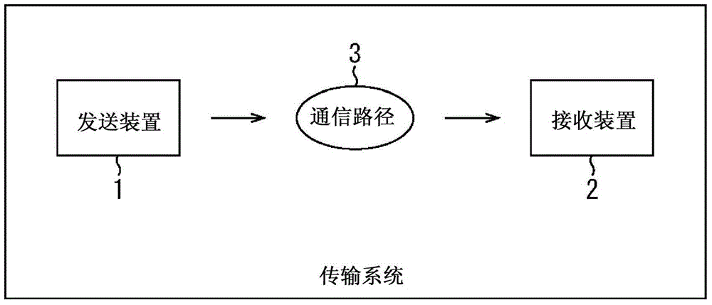
[0045] figure 1 is a block diagram showing one configuration example of an embodiment of a transmission system to which the present technology is applied (the system represents a logical collective of a plurality of devices, and each included device may or may not be in the same housing).

[0046] exist figure 1 , the transmission system includes a sending device 1 and a receiving device 2.

[0047] For example, the transmission device 1 transmits (broadcasts) (transmits) a program of television broadcasting through, for example, a communication path 3 (for example, a satellite line, a ground wave, or a cable (wire line)).

[0048] That is, the transmission device 1 is a transmission device conforming to, for example, DVB-T2, and transmits image data, audio data, etc. as a program using a DVB-T2 signal as transmission target data to be transmitted. Here, when the transmission device 1 is a transmission device conforming to DVB-T2, the communication path 3 is a gro...


PUM


Abstract

This technique relates to a reception apparatus, a reception method and a program that allow for preventing erroneous detection of a predetermined signal, such as, for example, a P1 signal, included in a received signal, such as, for example, a DVB-T2 signal. A correlation calculation unit determines a correlation value between received signals each including a predetermined signal in which an original signal and a duplicate signal, which is obtained from a copy of at least part of the original signal, are located. An average power calculation unit determines an average power of the received signals. A normalization unit uses the average power of the received signals to normalize the correlation value, thereby determining a normalized correlation value. This technique can be applied to, for example, a case of detecting, from a received signal of DVB-T2, a P1 signal that is a preamble signal.

Description


Claims


Application Information

Patent Timeline
Owner SONY CORP
Why Eureka
Try Eureka