Object detection device and object detection method

a technology of object detection and object detection, applied in the field of object detection apparatuses and object detection methods, can solve the problems of difficult to completely prevent merged detections or erroneous separated detections, and achieve the effect of preventing merged detections and improving object detection accuracy

Inactive Publication Date: 2013-12-19
PANASONIC INTELLECTUAL PROPERTY MANAGEMENT CO LTD
View PDF16 Cites 30 Cited by
  • Summary
  • Abstract
  • Description
  • Claims
  • Application Information

AI Technical Summary

Benefits of technology

[0016]With the claimed invention, it is possible to provide an object detection apparatus and an object detection method that are capable of improving object detection accuracy by preventing erroneous merged detections.

Problems solved by technology

However, while it might be possible to prevent non-detection and erroneous detections through such detection threshold adjustments alone, it would be difficult to completely prevent erroneous merged detections or erroneous separated detections.

Method used


Image

  • Object detection device and object detection method
  • Object detection device and object detection method
  • Object detection device and object detection method

Examples


embodiment 1

[0040][Key Elements of Object Detection Processing Apparatus]

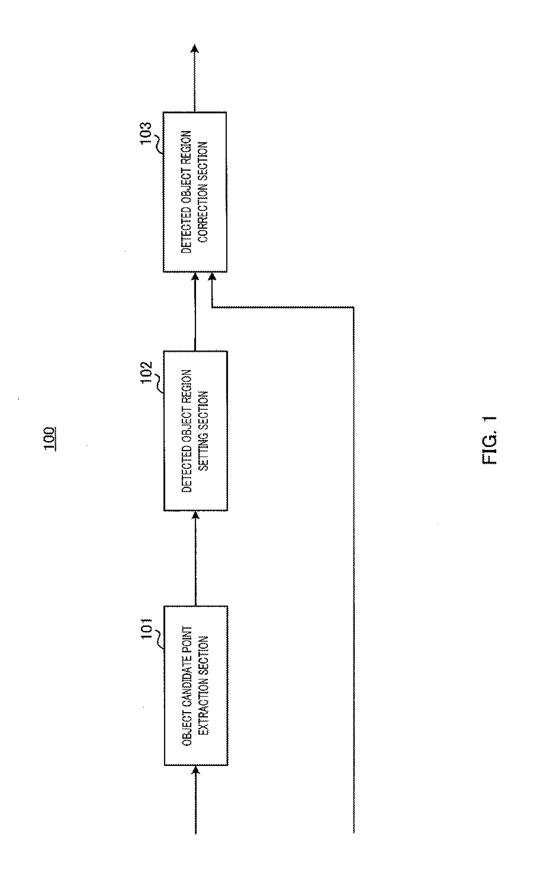
[0041]FIG. 1 shows key elements of object detection processing apparatus 100 according to Embodiment 1 of the claimed invention. With respect to FIG. 1, object detection processing apparatus 100 includes object candidate point extraction section 101, detected object region setting section 102, and detected object region correction section 103.

[0042]With respect to object detection processing apparatus 100, object candidate point extraction section 101 extracts candidate points from camera distance map information in which a set of coordinates in a base image plane are mapped to information regarding object presence at each coordinate obtained based on images taken with a stereo camera, the candidate points being defined by information regarding object presence of a predetermined value or greater and by coordinates mapped to the information regarding object presence of the predetermined value or greater. Alternatively, obje...

embodiment 2

[0114]In Embodiment 2, a filtering process is performed in advance on travel speed map information that is to be used for a detected object region correction process.

[0115]FIG. 12 shows elements of object detection apparatus 300 according to Embodiment 2 of the claimed invention. With respect to FIG. 12, object detection apparatus 300 includes filter section 301.

[0116]Filter section 301 performs a smoothing process on the travel speed map information generated by speed distribution generation section 209. This smoothes the speed value distribution of the travel speed map information in the (U′, parallax) plane. FIG. 13 shows an example of travel speed map information after a smoothing process.

[0117]The resolution of distance map information generated by a stereo camera is generally higher than the resolution of distance map information generated by a millimeter-wave radar. Accordingly, the distribution of travel speed map information obtained at coordinate conversion section 208 ten...

embodiment 3

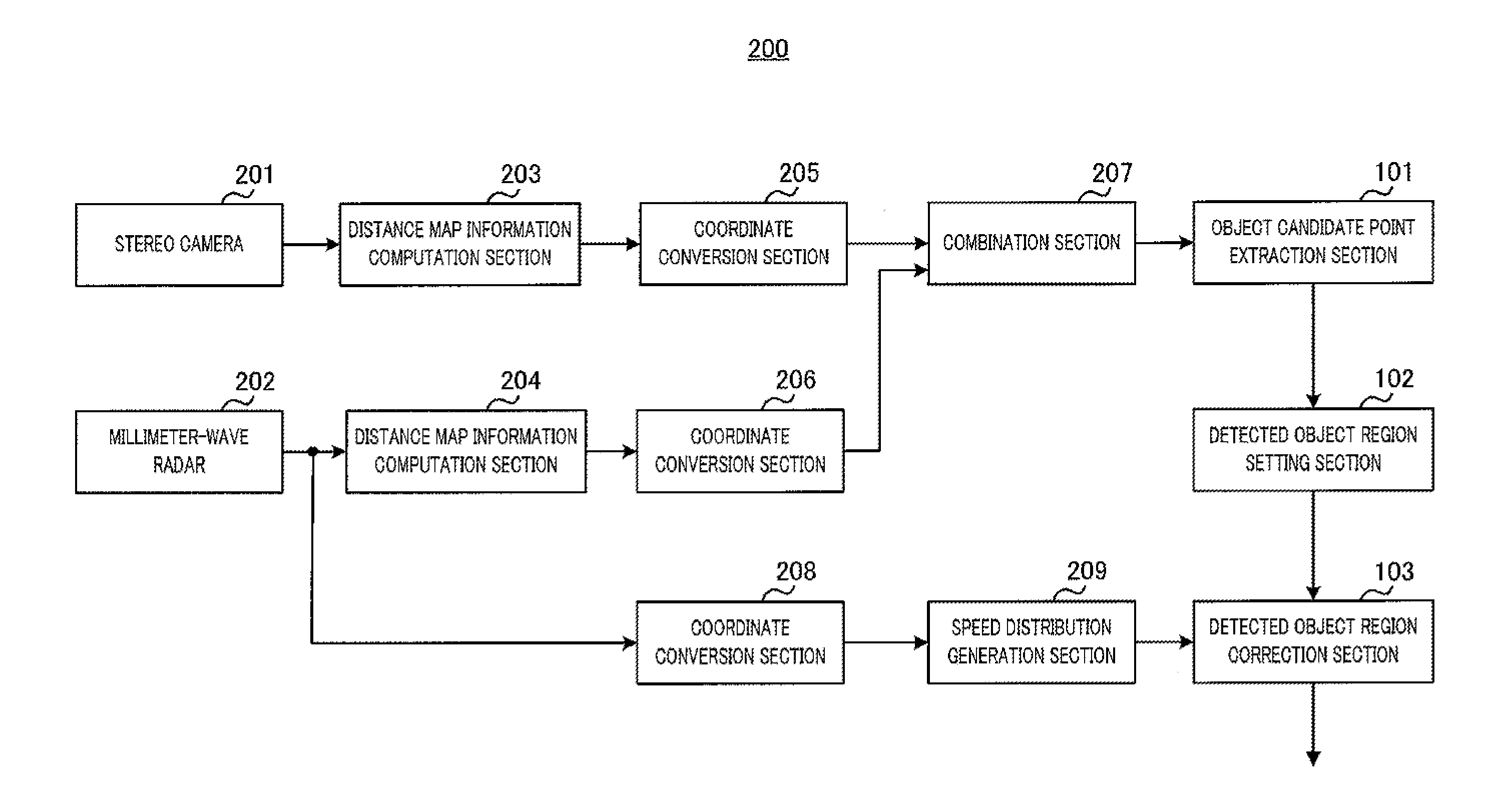
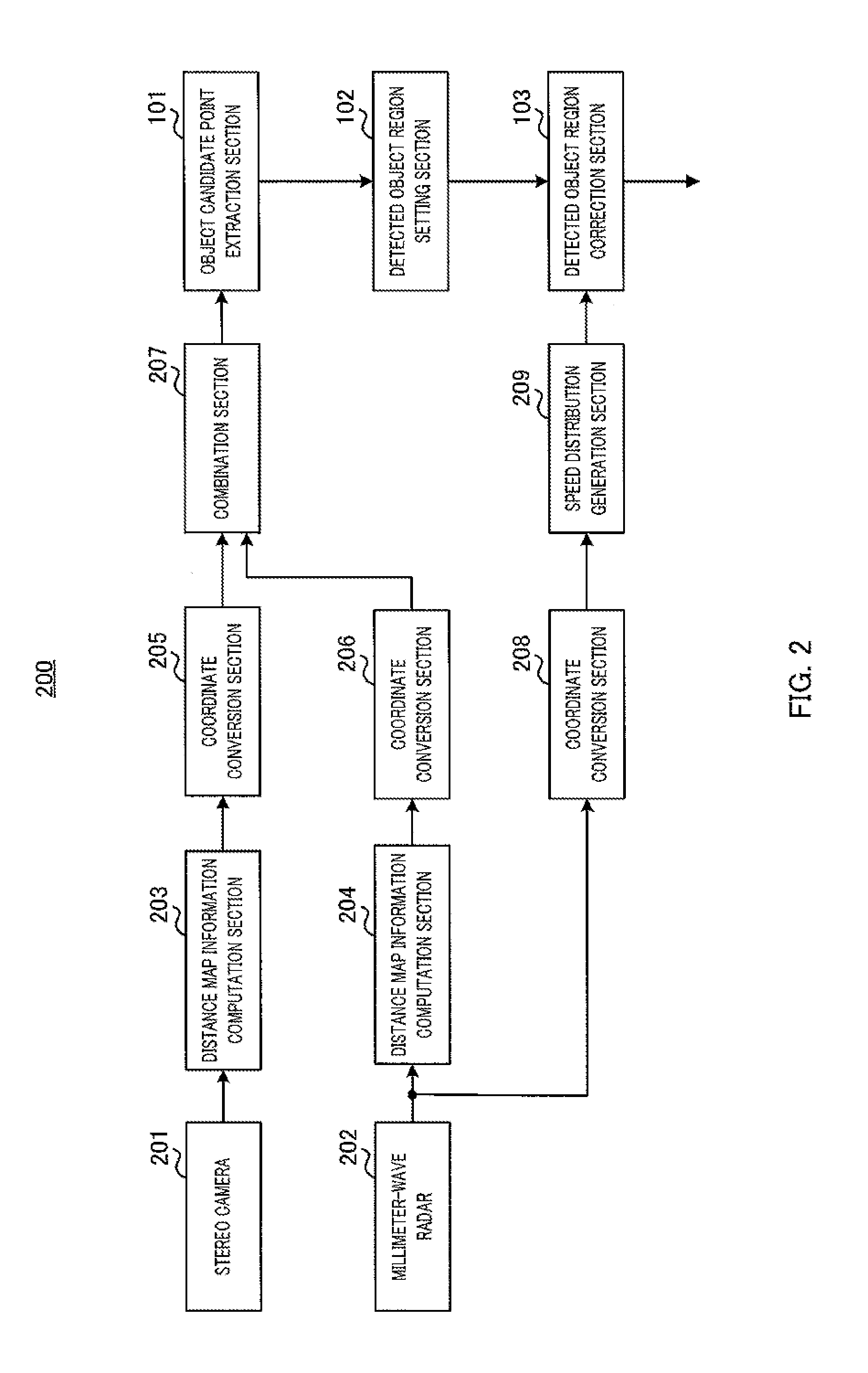
[0118]In Embodiment 3, in addition to an erroneous merge correction process, a detected length correction process is performed as a detected object region correction process. Processes described in connection with Embodiment 3 are applicable to both Embodiment 1 and Embodiment 2. Basic elements of an object detection apparatus according to Embodiment 3 are similar to those of object detection apparatus 200 according to Embodiment 1. As such, a description will be provided with reference to FIG. 2.

[0119]As shown in FIG. 14, detected object region correction section 103 of object detection apparatus 200 with respect to Embodiment 3 includes erroneous merge correction processing section 131 and detected length correction processing section 141.

[0120]Detected length correction processing section 141 performs generally the same processes as erroneous merge correction processing section 131 on each of a plurality of detected object regions divided at erroneous merge correction processing ...


PUM


Abstract

Disclosed is an object detection device capable of improving object detection accuracy by preventing erroneous combination detection. In this device, a detection object region correction unit (103) corrects a detection object region set by a detection object region set unit (102) on the basis of moving speed map information associated with a coordinate group in a reference image plane and the detected moving speed on each coordinate, which is detected by a radar. Thus, the detection object region can be amended by the use of the moving speed map information even when the detection object region is obtained as a result of erroneous combination. As a result, the object detection accuracy can be improved.

Description

TECHNICAL FIELD[0001]The claimed invention relates to object detection apparatuses and object detection methods.BACKGROUND ART[0002]There has been proposed an object positioning detection apparatus that uses both a millimeter-wave radar and a stereo camera. With object detection apparatuses, in general, the following may occur: being unable to detect an object even though it is located within a detection target area (i.e., non-detection); detecting an object in a detection target area when none is present (i.e., an erroneous detection); or managing to detect an object, but detecting a plurality of objects as a single object (i.e., an erroneous merged detection) or detecting a single object as a plurality of objects (i.e., erroneous separated detections).[0003]In an effort to avoid such detection failures, detection thresholds are adjusted, for example. With millimeter-wave radars, such detection thresholds are set with respect to wave reflection intensity, and with stereo cameras, t...

Claims


Application Information

Patent Timeline
Patent Type & Authority Applications(United States)
IPC IPC(8): G01S13/86
CPCG01S13/867G01V8/10G08G1/04G08G1/052G01S13/86G06V20/653G06V20/54G06V10/255G06V10/811G06F18/256G01S13/04G01S7/414G01S13/56G01S13/52G01S7/295G01S7/41G01S7/292
Inventor YASUGI, MAKOTONISHIMURA, HIROFUMI
Owner PANASONIC INTELLECTUAL PROPERTY MANAGEMENT CO LTD
Why Eureka
Try Eureka