Automatic door sensor device

a door sensor and automatic technology, applied in the direction of door/window fittings, building components, construction, etc., can solve the problems of inability to easily perceive the limit within which an object can be detected by the microwave sensor, the infrared sensor mounted on the transom may malfunction, and the inability to accurately detect objects

Active Publication Date: 2015-03-05
OPTEX CO LTD
View PDF19 Cites 33 Cited by
  • Summary
  • Abstract
  • Description
  • Claims
  • Application Information

AI Technical Summary

Benefits of technology

[0012]According to this configuration, it is possible, by changing the detection area, to prevent erroneous detection of the movement of the door and erroneous detection resulting, for example, from the swaying of the support member on which the door is mounted. In particular, erroneous detection is prevented by temporarily changing the detection area while the door is transitioning from an open position to a closed position, whereas the detection area is normally defined so as not to fail to detect an object.
[0016]According to this configuration, the first moving object detection area serving as the normal detection area is allowed to be set to a range including the area on the track of the door, and it is therefore not necessary to set the detection direction of the moving object sensor outward away from the area on the track of the door. Accordingly, the moving object detection area can be overlapped with the area on the track of the door, thus improving the reliability of detection especially when different detection methods are used for the moving object sensor and the doorway area sensor. On the other hand, when it is determined, by using the doorway area sensor, that the door is transitioning from an open position to a closed position, the moving object detection area is changed so as to be changed to the second moving object detection area. Since the second moving object detection area does not overlap with the area on the track of the door, it is possible to avoid erroneously detecting the door that is transitioning from an open position to a closed position as the movement of an object.
[0018]Since the moving object detection area of the moving object sensor is changed by only changing the threshold of the detection signal, the moving object detection area can be switched by a simple process.
[0022]According to this configuration, even if the support member of the door sways while the door is transitioning from an open position to a closed position, it is possible to prevent erroneous detection resulting from that swaying.
[0024]According to a preferred embodiment, when a predetermined period has elapsed after the detection area is changed upon determination that the door is transitioning from the open position to the closed position, the detection area changer returns the changeable detection area to the detection area before the change. According to this configuration the detection area is changed temporarily, and thus reliable detection can be performed in a normal state.

Problems solved by technology

In the automatic door sensor device, the microwave sensor may erroneously recognize the closing door as a moving object in the case that the detection area of the microwave sensor overlaps with the area on the track of the door.
However, the detection area of the microwave sensor, or in other words, the limit within which an object can be detected by the microwave sensor cannot be readily perceived.
Further, in the event that a transom that supports the door sways while the door is transitioning from an open position to a closed position, the infrared sensor mounted on the transom may malfunction and the automatic door sensor device may try to open the door in order to prevent an object from being jammed in the door, even though there is no object in the area.
If the infrared sensor is configured in terms of preventing this malfunction, the infrared sensor would fail to detect an object in a normal detection operation.

Method used


Image

  • Automatic door sensor device
  • Automatic door sensor device
  • Automatic door sensor device

Examples


Embodiment Construction

[0038]Hereinafter, an automatic door sensor device according to a first embodiment of the present invention will be described with reference to the drawings.

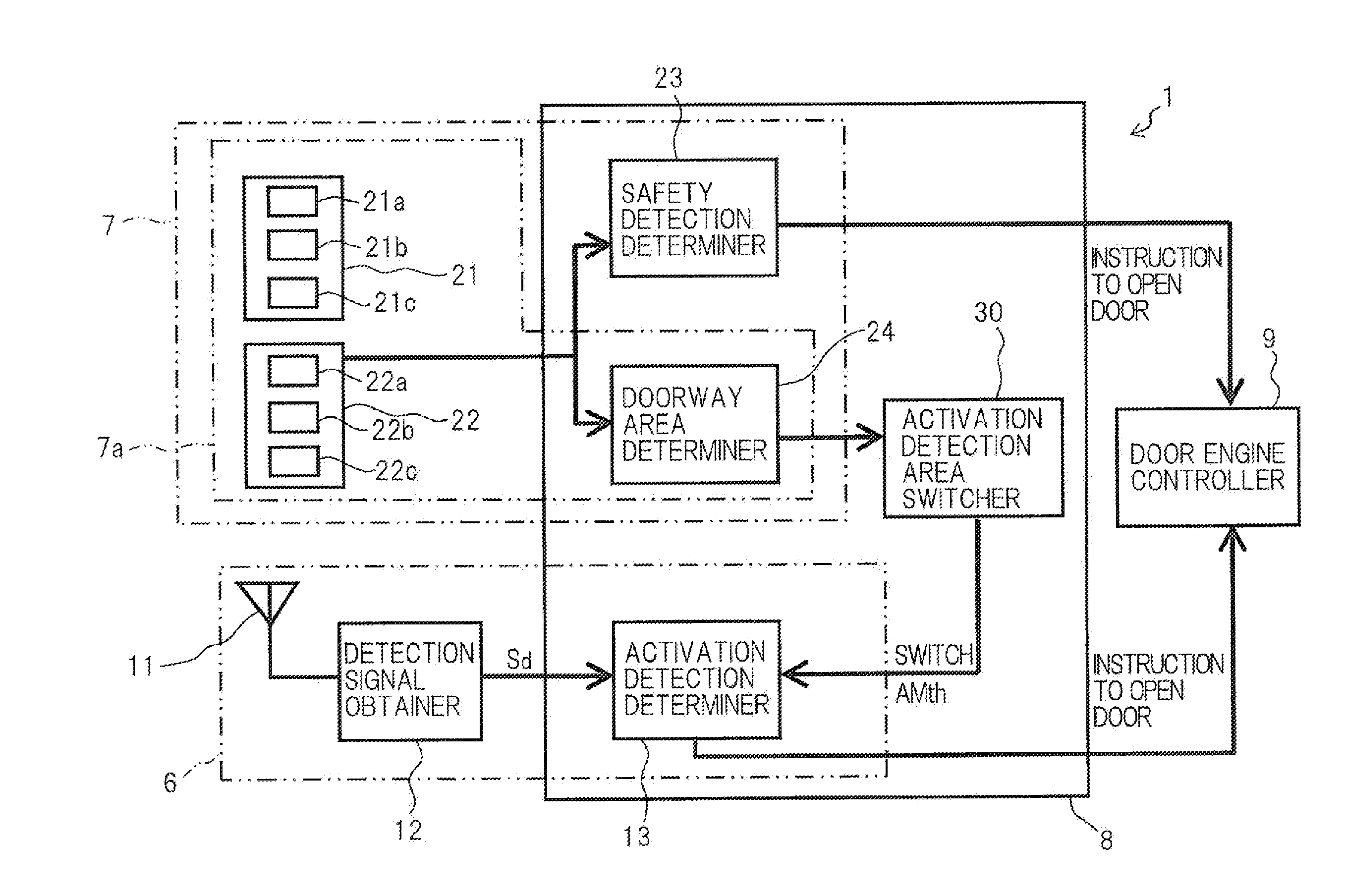
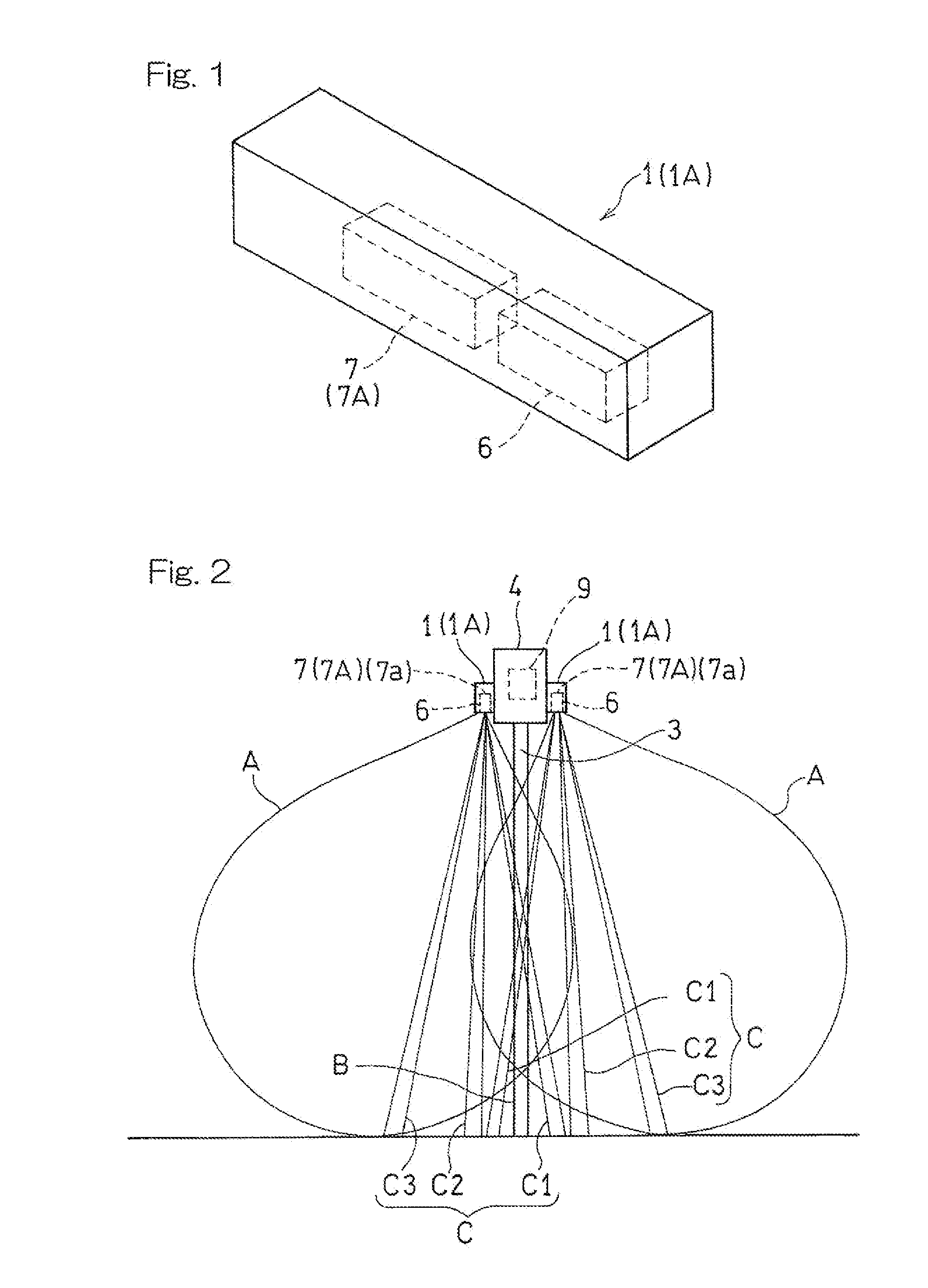
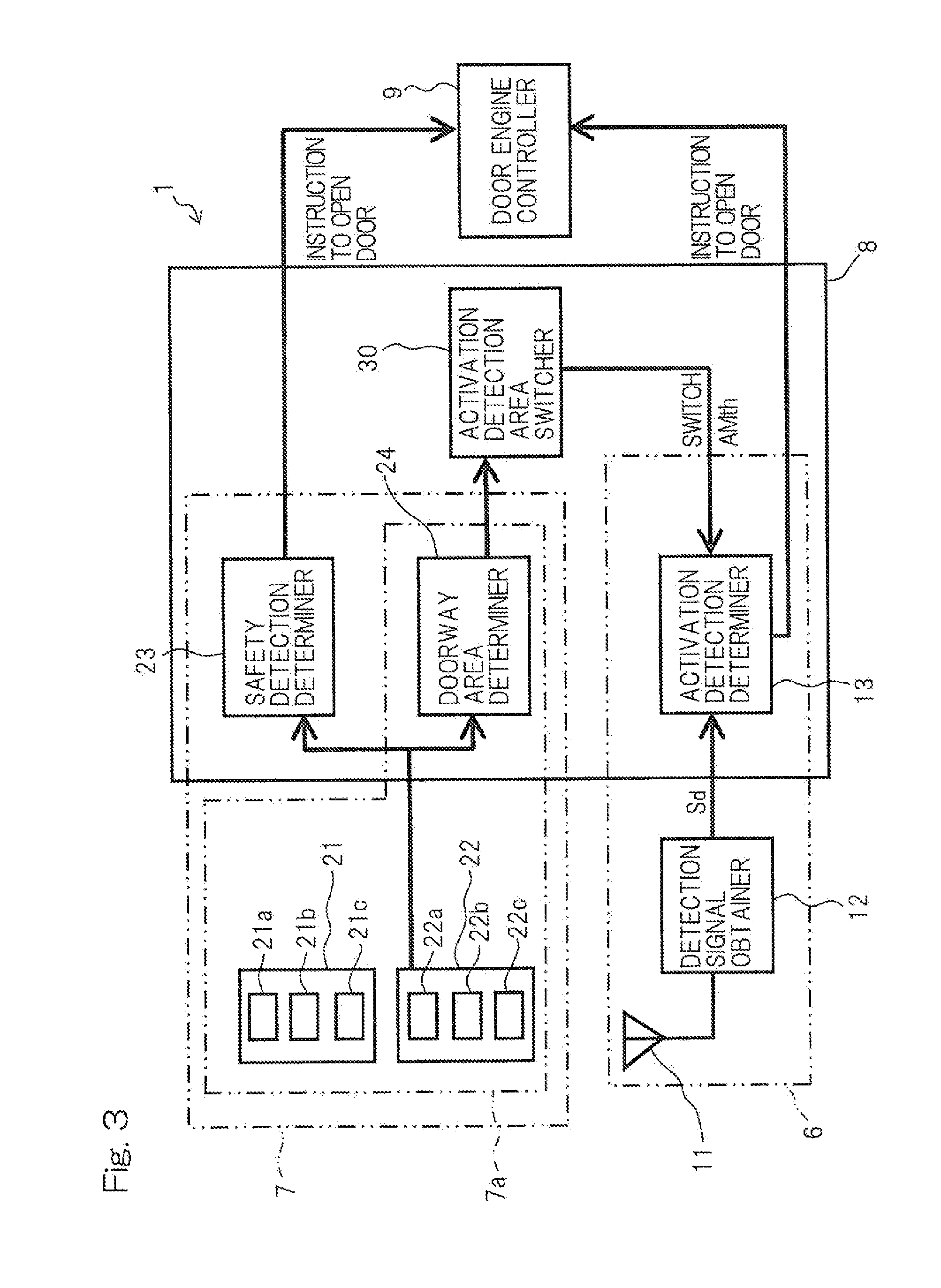
[0039]FIGS. 1 and 2 show the automatic door sensor device according to the first embodiment of the present invention and detection areas thereof. The automatic door sensor device 1 according to the present embodiment shown in FIG. 1 is attached, for example, to the inner-side face and the outer-side face of a transom (support member) 4 supporting the upper end of a sliding automatic door 3 shown in FIG. 2. The device 1 detects an object, so that opening and closing of the automatic door 3 are selectively controlled. The automatic door sensor devices 1, 1 are connected to a controller 9 of a door engine (not shown) accommodated within the transom 4. These two automatic door sensor devices 1, 1 are substantially identical, and therefore, only one of the sensors will be described in the following. It should be noted that the automa...


PUM


Abstract

There is provided an automatic door sensor device (1) capable of preventing a door (3) which is transitioning from an open position to a closed position from being erroneously detected as an object by temporarily changing a detection area (A, C2, C3). The automatic door sensor device (1) includes a doorway area sensor (7a) that detects the presence of an object in a doorway area (B) which includes at least a portion of an area defined by the path of a door (3), detectors (6, 7b) that detect the presence and / or the movement of an object in changeable detection areas (A, C2, C3), and a detection area changer (31) that changes the detection areas (A, C2, C3) when it is determined, by using the doorway area sensor (7a), that the door (3) is transitioning from an open position to a closed position.

Description

CROSS REFERENCE TO THE RELATED APPLICATION[0001]This application is based on and claims Convention priority to Japanese patent application No. 2013-177889, filed Aug. 29, 2013, the entire disclosure of which is herein incorporated by reference as a part of this application.BACKGROUND OF THE INVENTION[0002]1. Field of the Invention[0003]The present invention relates to an automatic door sensor device that detects an object to control opening and closing of a door.[0004]2. Description of Related Art[0005]In general, a microwave sensor is often used for detecting the entry of an object such as a human body into a detection area. As a result of this detection, an automatic door is opened. In order to ensure the safety of an area on the track of the door or on the path of movement of the door, an infrared sensor is used to detect an object in a doorway area which includes at least a portion of the area defined by the path of the door, and the door is kept open until the object leaves the...

Claims


Application Information

Patent Timeline
Patent Type & Authority Applications(United States)
IPC IPC(8): E05F15/00E05F15/10
CPCE05F15/0026E05F15/0004E05F2015/0043E05F2015/0034E05F15/10E05F15/40E05F15/73E05Y2900/132
Inventor IWATA, YOHEISHIRAISHI, MASANAOIKEDA, TAKAYASUKONDO, TAKASHI
Owner OPTEX CO LTD
Why Eureka
Try Eureka