Object direction detection method and apparatus for determining target object direction based on rectified wave phase information obtained from plurality of pairs of receiver elements

a receiver element and object direction technology, applied in the direction of reradiation, measurement devices, instruments, etc., can solve the problems of large apparatus size, difficulty in reducing the distance between adjacent receiver elements that is less than /2, etc., and achieve the effect of preventing the error of direction detection due to virtual images and large scal

Inactive Publication Date: 2008-02-28
DENSO CORP +1
View PDF11 Cites 36 Cited by
  • Summary
  • Abstract
  • Description
  • Claims
  • Application Information

AI Technical Summary

Benefits of technology

[0014] It is an objective of the present invention to overcome the above problem of the prior art by providing a direction detection method, with the method being suitable for execution by a computer program, and an object detection apparatus for implementing the direction detection method, whereby the direction of a target object can be detected both for azimuth angle and altitude angle, while erroneous detection of directions due to virtual images can be prevented, without requiring that the apparatus be large in scale.

Problems solved by technology

However in practice, the diameter of each receiver element must be greater than λ / 2, so that it is difficult to make the distance between adjacent receiver elements smaller than λ / 2.
Hence, the apparatus becomes large in scale.

Method used


Image

  • Object direction detection method and apparatus for determining target object direction based on rectified wave phase information obtained from plurality of pairs of receiver elements
  • Object direction detection method and apparatus for determining target object direction based on rectified wave phase information obtained from plurality of pairs of receiver elements
  • Object direction detection method and apparatus for determining target object direction based on rectified wave phase information obtained from plurality of pairs of receiver elements

Examples


first embodiment

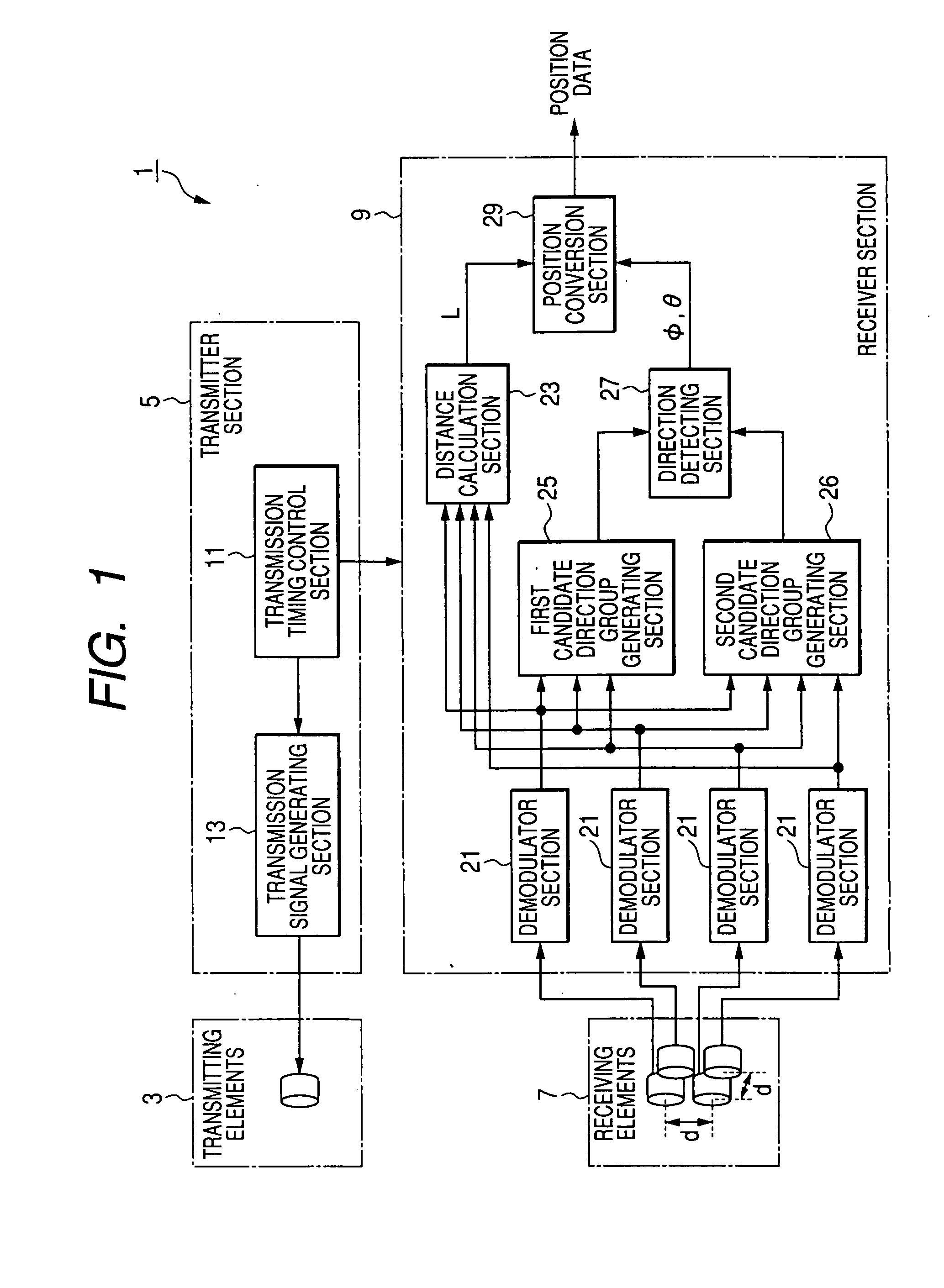
[0080]FIG. 1 is a block diagram showing the overall configuration of a first embodiment, which is an object detection apparatus 1. The object detection apparatus 1 transmits pulses of ultrasonic waves and receives resultant reflected ultrasonic wave pulses from an object to obtain received signals, and generates position data expressing the location of the object within three dimensions, based on the received signals.

[0081] In this type of the direction detecting apparatuses, an operating principle for detecting the target obstacle direction in which the target object is located uses so called the triangulation method schematically described in FIG. 23. In this triangulation method for detecting a target object located on a two-dimensional plane, a transmitting wave such as a radio wave, an ultrasonic wave, and the like is transmitted towards possible directions in which it is expected that the target object exists from the direction detecting apparatus. If the target object exists...

second embodiment

[0150] A second embodiment will be described in the following. This embodiment differs from the first embodiment only with respect to the configuration of a first candidate group generating section 25a which replaces the first candidate group generating section 25 of the first embodiment, so that the description will be centered on these points of difference from the first embodiment.

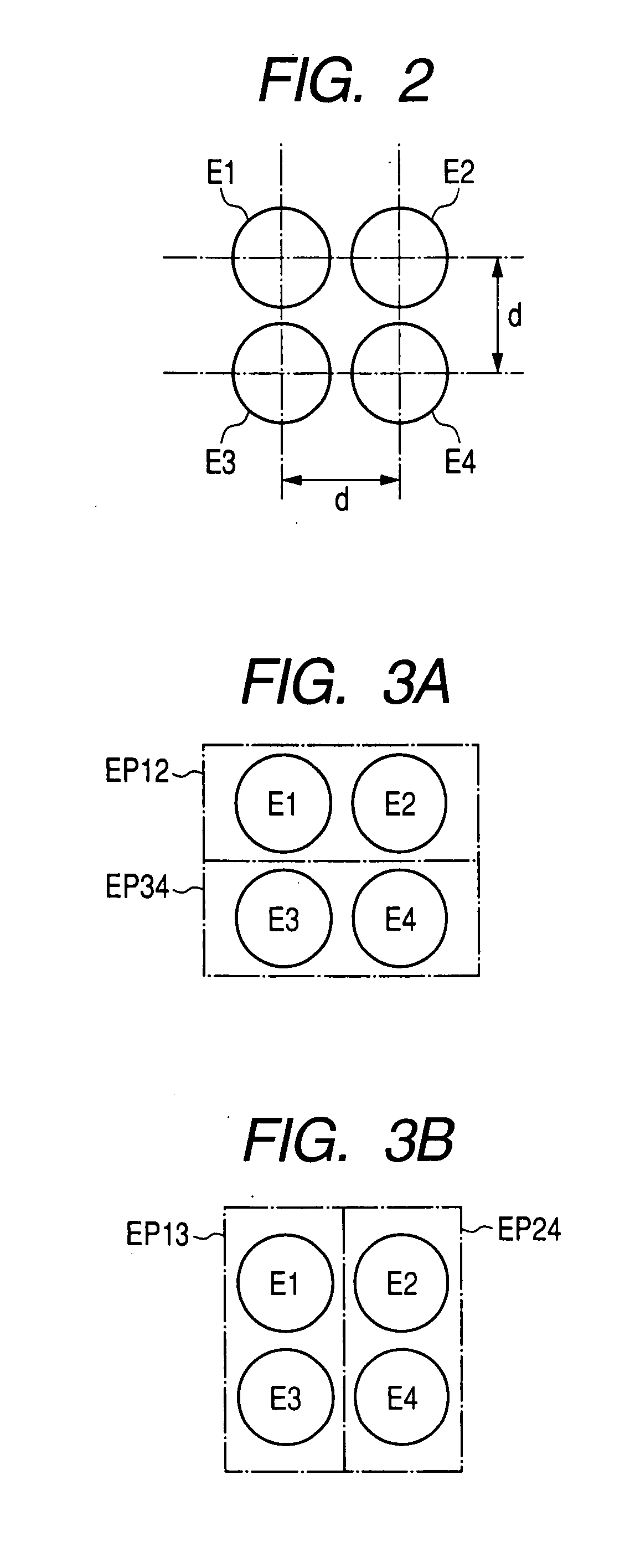
[0151]FIG. 8 is a block diagram of the second embodiment. As shown, the first candidate group generating section 25a includes a phase difference calculation section 31 which calculates the phase difference ΔΦ1,2 between the demodulated signals R1, R2, a phase difference calculation section 32 which calculates the phase difference ΔΦ3,4 between the demodulated signals R3, R4, a phase difference calculation section 33 which calculates the phase difference ΔΦ1,3 between the demodulated signals R1, R3, and a phase difference calculation section 34 which calculates the phase difference ΔΦ2,4 between the dem...

third embodiment

[0155] A third embodiment will be described in the following. This embodiment differs from the first embodiment only with respect to a part of the processing executed by the direction determining section 27, so that the description will be centered on these points of difference from the first embodiment.

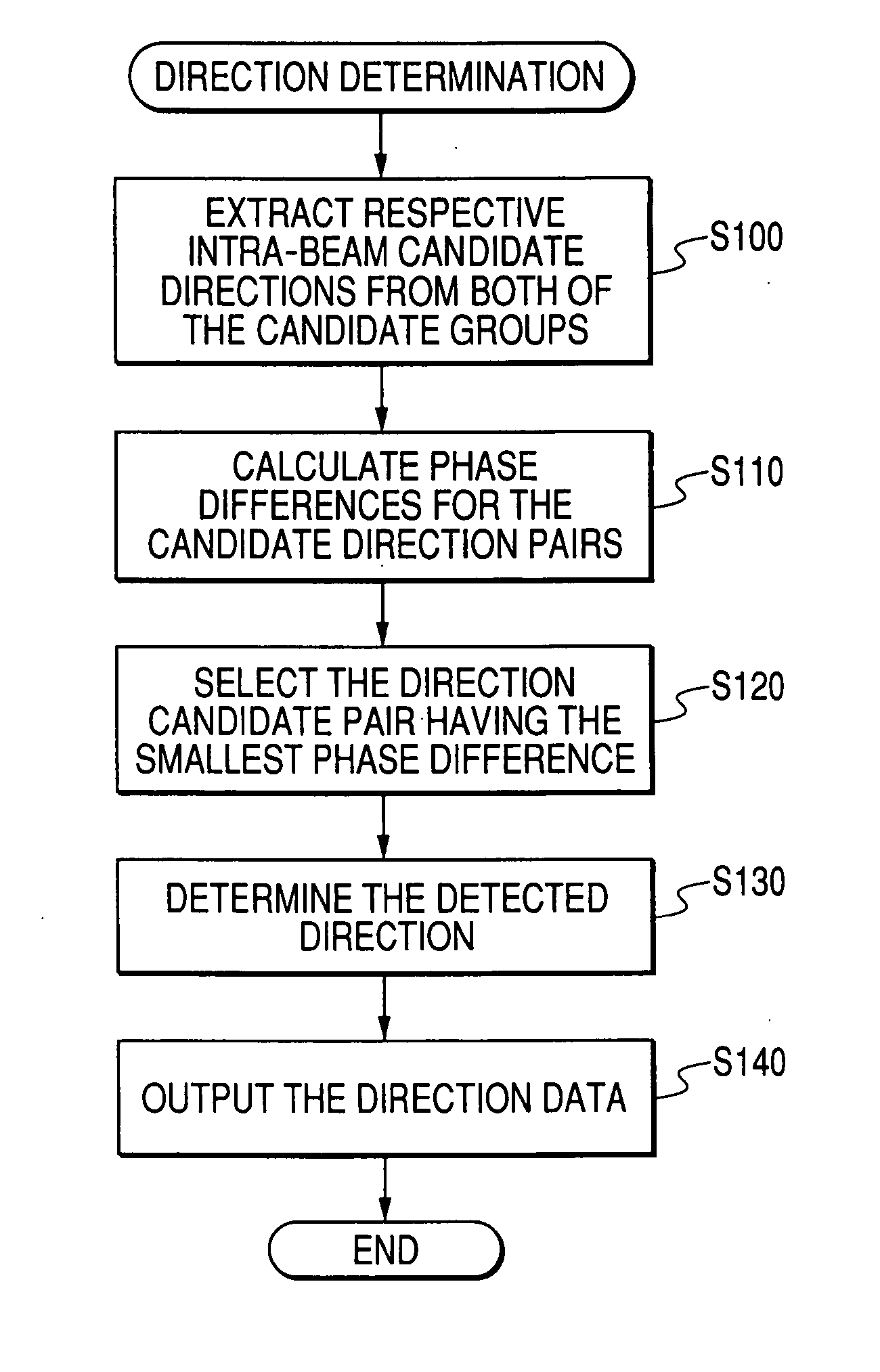
[0156]FIG. 9 is a flow diagram of the processing executed by the direction determining section 27 of this embodiment. As shown in FIG. 9, by comparison with the first embodiment, S100 is omitted and S135 and S150 are added.

[0157] When processing is started, then firstly in S110, a plurality of candidate direction-pairs are derived. Each of these is a combination of one direction from the first candidate direction group and one direction from the second candidate direction group, i.e., with all of the possible different direction pairs being derived. The amount of difference in direction between the constituent directions in each of these candidate direction-pairs is then derived, f...


PUM


Abstract

A method of detecting a direction of a target object based on received signals from a receiver element section which receives reflected waves comprising probe waves reflected from said target object, wherein said receiver section comprises an array of four receiver elements with at least three of said receiver elements located at respective apexes of a square, said square having a side length that is equal to or greater than half of a wavelength of said probe waves, includes selecting a specific one of said candidate directions based upon respective phase differences of a plurality of pairs of said receiver elements, with said plurality of pairs comprising at least one pair that differs from each of said pairs of receiver elements utilized in deriving said plurality of candidate directions, and deriving said azimuth angle and said altitude angle of said target object.

Description

CROSS REFERENCE TO RELATED APPLICATION [0001] The present application relates to and incorporates by references Japanese Patent Application No. 2006-231084 filed on Aug. 28, 2006 and No. 2007-147017 filed on Jun. 1, 2007. BACKGROUND OF THE INVENTION [0002] 1. The Field of the Invention [0003] The present invention relates to a method of detecting the direction of an object by transmitting probe waves and receiving resultant reflected waves from the object, and to an apparatus and program for applying the detection method. [0004] 2. Description of the Prior Art [0005] Types of apparatus are known in the prior art for detecting the position of an object by transmitting probe waves such as ultrasonic waves during a fixed interval, receiving the resultant reflected waves from the object at an array of receiver elements, and utilizing the phase differences between the signals received by respective receiver elements to detect the direction of the object. [0006] The term “receiver element...

Claims


Application Information

Patent Timeline
Patent Type & Authority Applications(United States)
IPC IPC(8): G01S13/00
CPCG01S3/808G01S15/89G01S15/42G01S7/526
Inventor MATSUURA, MITSUYASUHATTORI, TOSHIHIROFUJITA, MITSURU
Owner DENSO CORP
Why Eureka
Try Eureka