
Tool for rapidly fixing grout sleeve and using method of tool

A grouting sleeve and rapid technology, applied in the processing of building materials, structural elements, building components, etc., can solve the problems of complex operation and inconvenient operation, and achieve the effect of precise and efficient positioning, simple structure and coherent operation process

Active Publication Date: 2016-01-20
SHENZHEN CITY MODERN BUILDING SCI & TECH
View PDF10 Cites 5 Cited by
  • Summary
  • Abstract
  • Description
  • Claims
  • Application Information

AI Technical Summary

Problems solved by technology

[0003] The grouting sleeve and the steel bar are connected by pouring concrete, but the grouting sleeve needs to be installed and fixed. The current tooling method is only realized by using traditional tools, and the traditional tools are complicated and inconvenient to operate

Method used


Image

  • Tool for rapidly fixing grout sleeve and using method of tool
  • Tool for rapidly fixing grout sleeve and using method of tool
  • Tool for rapidly fixing grout sleeve and using method of tool

Examples


Embodiment 1

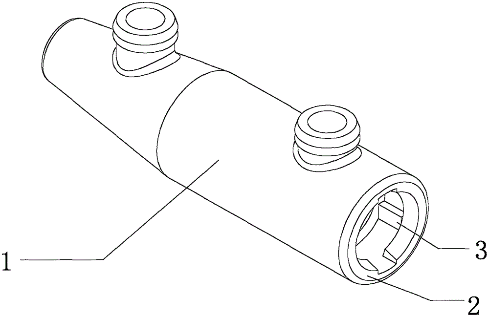
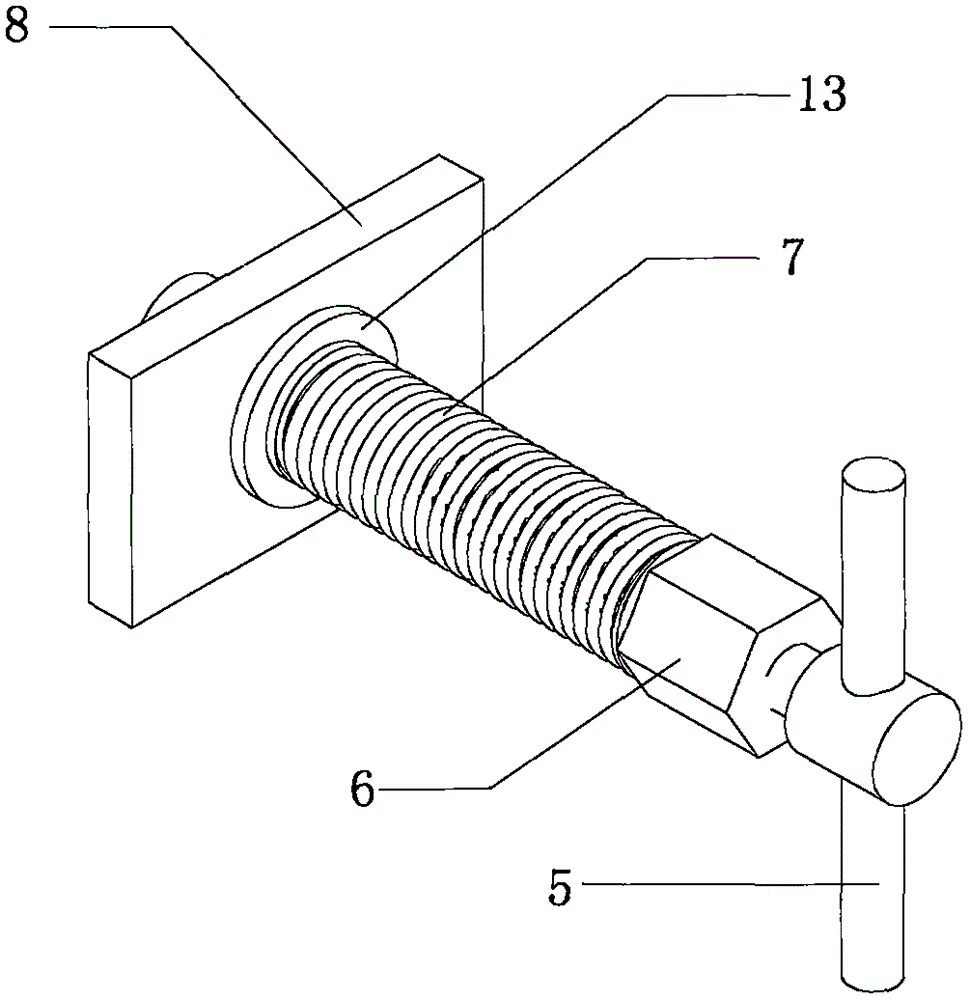
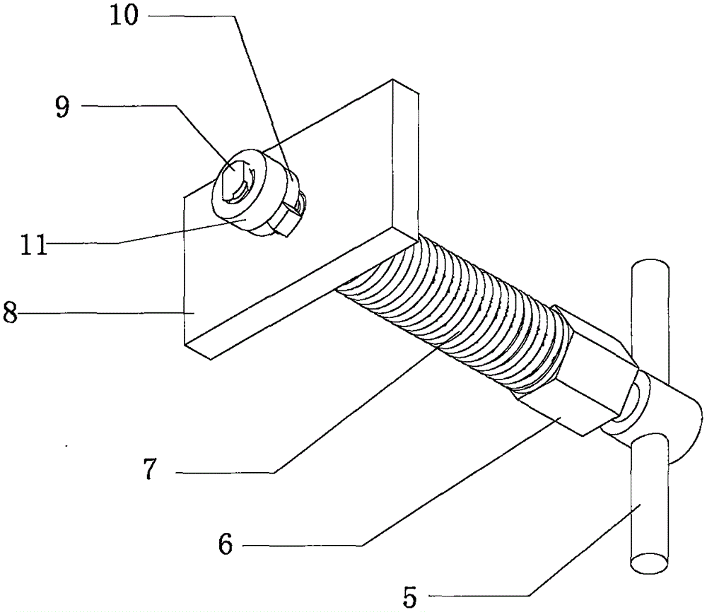
[0030] like Figure 2 to Figure 7 As shown in the figure, a tooling tool for quickly fixing a grouting sleeve includes a bolt 4 with a rolling thread. Cap 6, the bolt 4 at the lower end of the adjusting nut 6 is covered with a spring member 7, the bolt 4 at the lower end of the spring member 7 is provided with a template 8, the bottom of the bolt 4 is provided with a waist-shaped wire head 9, and the waist-shaped wire head 9 is fixed on the sleeve After clamping the board 10, use the fastening nut 11 to fix it.

[0031] A first spring washer (not visible in the figure) is arranged between the fixing card 10 and the fastening nut 11 .

[0032] A limiting collar 12 is also set between the lower part of the spring member 7 and the bolt 4 . A protruding outer limiting ring 13 is provided on the outer side of the lower end of the limiting collar 12 , and the outer limiting ring 13 serves as a washer for supporting the spring member 7 to move or slide on the bolt 4 .

[0033] The...

Embodiment 2

[0035] like Figure 8 As shown, a tool for quickly fixing a grouting sleeve includes a bolt 4' with rolling threads, characterized in that a handle 5' is installed at the top of the bolt 4', and a bolt 4' faces downward along the handle 5' There is an adjustment nut 6' on the upper end, the bolt 4' at the lower end of the adjustment nut 6' is covered with a spring member 7', the bolt 4' at the lower end of the spring member 7' is provided with a template 8', and the bottom of the bolt 4' is provided with a waist Shaped wire head 9', waist-shaped wire head 9' is put on the fixing card 10', and then fixed with the fastening nut 11'.

[0036] A second spring washer 16' is arranged between the spring member 7' and the template 8' as a washer for supporting the spring member 7' to move or slide on the bolt 4'.

[0037] In addition, in order to prevent the spring from clamping the hand during construction, an anti-clamping hand ring sleeve may be provided on the bolt at the lower e...


PUM


Abstract

The invention discloses a tool for rapidly fixing a grout sleeve. The tool comprises a bolt with a tolled thread, and is characterized in that a handle is mounted at the top end of the bolt; an adjusting nut is downwards arranged on the bolt along the handle; the bolt at the lower end of the adjusting nut is sleeved with a spring part; a template is arranged on the bolt at the lower end of the spring part; a waist-shaped thread head is arranged at the bottom of the bolt; after the waist-shaped thread head is sleeved with a fixing clamp plate, a fastening nut is used for fixing; the waist-shaped thread head is pushed through a steel bar insertion end at the bottom of the grout sleeve; the handle is rotated to drive the fixing clamp plate rotationally reach to a clamp point in the grout sleeve; after the handle is released, the bottom surface of the grout sleeve clings to the surface of the template under the reset pressure of the spring part. The tool has the advantages that the operation process is very coherent, no very complex working procedure is needed, the positioning is precise and efficient, the own structure is simple, the manufacturing cost is low, and the use is convenient.

Description

【Technical field】 [0001] The invention relates to a tooling tool for quickly fixing a grouting sleeve and a method of using the same. 【Background technique】 [0002] With the advancement of residential industrialization in my country, prefabricated buildings are emerging, and a large number of projects use prefabricated structures, and a large number of grouting sleeves are required in prefabricated shear walls and prefabricated columns. The steel bars cast in the concrete can work together with the solidified concrete to form a solid reinforced concrete structure. The use of grouting sleeves to connect longitudinal steel bars between prefabricated components is a better research direction at present. [0003] The grouting sleeve and the steel bar are connected by pouring concrete, but the grouting sleeve needs to be installed and fixed. The current tooling method only uses traditional tools, which are complicated and inconvenient to operate. [0004] The above defects are ...

Claims


Application Information

Patent Timeline
IPC IPC(8): E04G21/12E04C5/16
Inventor 罗山峰谷明旺金波峰陈杰姚桂宁
Owner SHENZHEN CITY MODERN BUILDING SCI & TECH
Learn More